Apparatus for finishing stripped end of shield wire

Inactive Publication Date: 2005-04-26
YAZAKI CORP
View PDF11 Cites 2 Cited by
  • Summary
  • Abstract
  • Description
  • Claims
  • Application Information

AI Technical Summary

Benefits of technology

[0028]Preferably, the metal shell is inserted into the shield stopper with the knitted layer therebetween. Thus, the shield stopper partially overlies over the metal shell with the knitted layer therebetween, allowing an easy crimping of the metal shell.
[0029]Preferably, the

Problems solved by technology

However, the manual cutting of the knitted layer C causes an incompletely cut portion of the knitted layer C at the stage of FIG. 7D, causing variations in cutting quality thereof.
Furthermore, the pair of scissors E having sharp

Method used


Image

  • Apparatus for finishing stripped end of shield wire
  • Apparatus for finishing stripped end of shield wire
  • Apparatus for finishing stripped end of shield wire

Examples


Embodiment Construction

[0037]Referring to FIGS. 1 to 3, an embodiment of a method for finishing a shield wire according to the present invention will be discussed in detail.

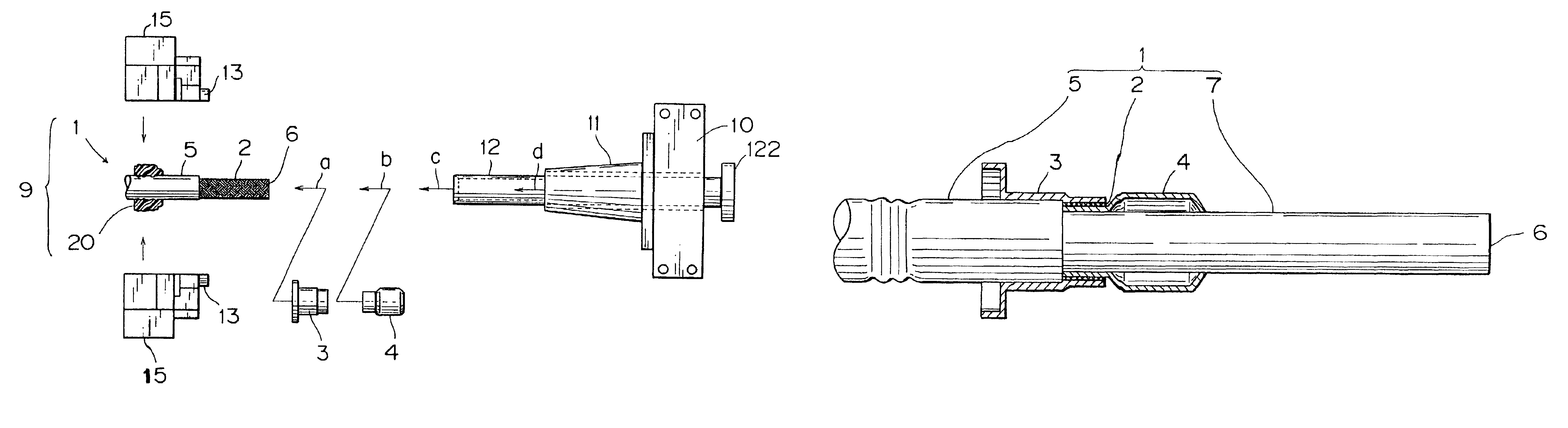
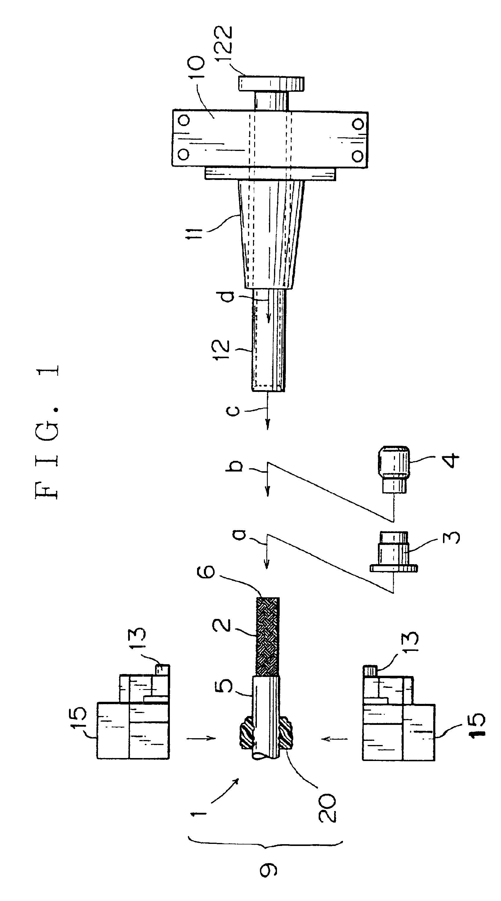
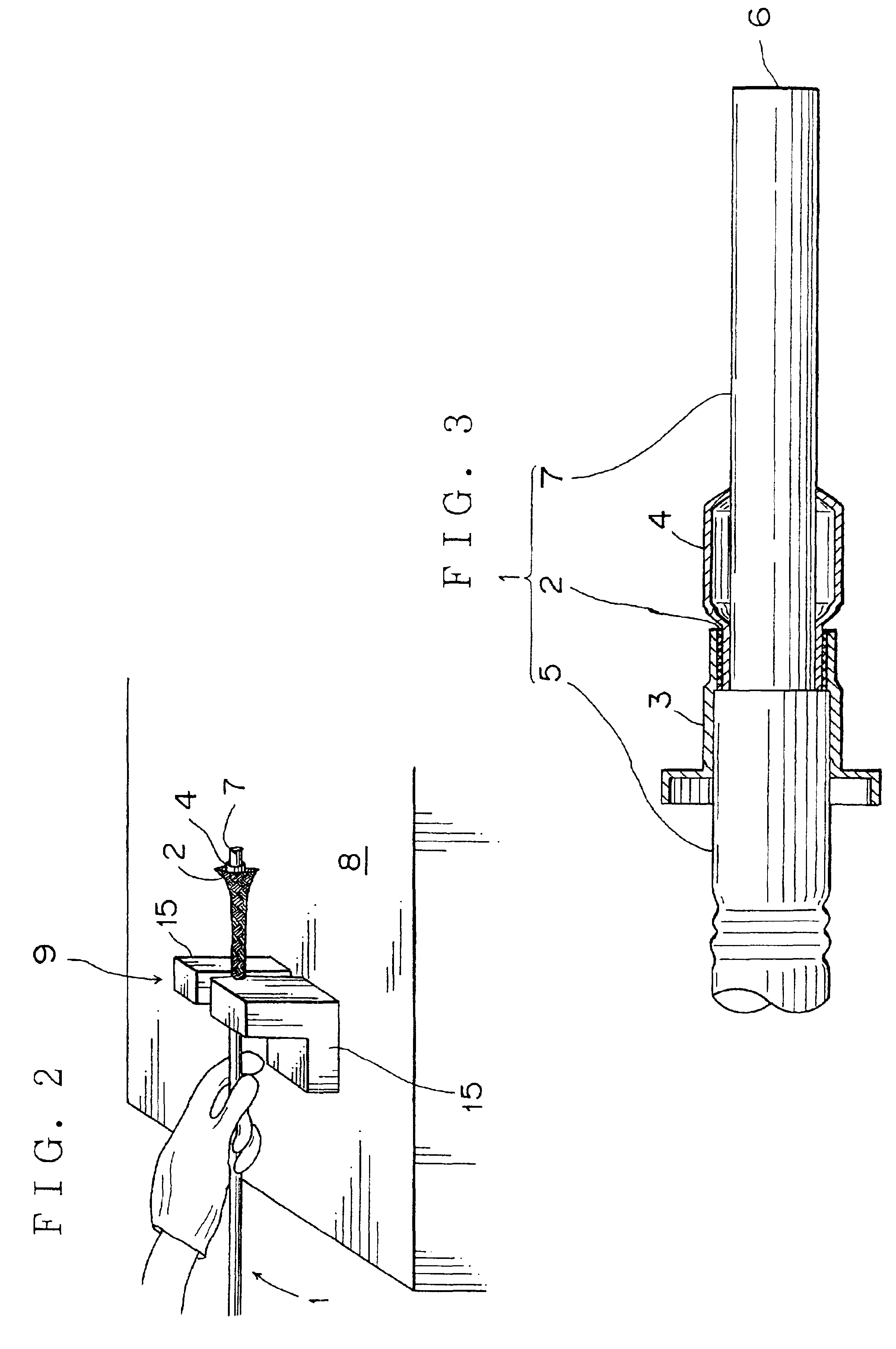
[0038]As illustrated in FIG. 3, a shield wire 1 is finished at an end thereof. The finished end is crimped by a shield stopper 3, while a knitted layer 2 of the shield wire 1 is pinched between a metal shell 4 and the shield stopper 3. First, as illustrated in FIG. 1, an outer sheath 5 of the shield wire 1 is stripped by a predetermined length from a cut end 6 of the wire to expose the knitted layer 2. Over the knitted layer 2, the shield stopper 3 is mated till the shield stopper 3 abuts against a stripped end of the outer sheath 5 in a direction a. Next, as illustrated in FIG. 2, an end portion of the exposed knitted layer 2 is expanded, and the metal shell 4 is mated over the inner sheath 7 in a direction b. Then, a clamp means 9 pinches the shield wire on a work table 8 by a manual operation.

[0039]Reference numeral 10 designates a ...


PUM

PropertyMeasurementUnit
Lengthaaaaaaaaaa
Areaaaaaaaaaaa

Abstract

An outer sheath of a shield wire is stripped by a predetermined length from an end of the shield wire to expose a knitted layer of the shield wire. A shield stopper is mated over the exposed knitted layer until the shield stopper abuts against a stripped end of the outer sheath. A metal shell piece is preparatorily mated over an inner sheath of the shield wire while the metal shell piece expands the knitted layer. The shield stopper is clamped by a clamp means, and the mated metal shell piece is pushed to engage with the shield stopper. In the engagement state, the shield stopper overlaps a forward end portion of the metal shell with the knitted layer therebetween. A first cutter is guided by a pipe member so that the first cutter engages with an outer peripheral surface of the second cutter. Thereby, the shearing movement of the cutters cuts the exposed knitted layer near a rear end of the shield stopper.

Description

BACKGROUND OF THE INVENTION[0001]1. Field of the Invention[0002]The present invention relates to a finishing method and an apparatus thereof for cutting a knitted layer of an end portion of a shield wire to automatically fit a shield stopper and a metal shell to the end potion.[0003]2. Related Art[0004]Recently, electric motor vehicles have been developed in view of nature conservation and environmental pollution problems. Such electric motor vehicles employ high voltage cables connected to a battery or a generator. The cable is a shield wire of which an end is finished as mentioned below. That is, as illustrated in FIGS. 7A to 7B, an outer sheath A of the shield wire is manually cut off by a predetermined length L from a cut end B to expose a knitted layer C. Over the exposed shied wire, a shield stopper D of a metal conductor is mated to abut against an end surface of the outer sheath A (FIG. 7B). Then, a pair of scissors E cut off an unnecessary portion of the exposed knitted lay...

Claims


Application Information

Patent Timeline
IPC IPC(8): H02G15/02H02G15/068H01R43/048H01R43/04H01R43/042H02G1/12H02G1/14
CPCH01R43/048H02G15/068H01R43/0421Y10T29/49174Y10T29/49192Y10T29/49188Y10T29/53213Y10T29/5187Y10T29/532Y10T29/53261
Inventor SATO, TAKAHIKOKOBAYASHI, HIROKAZUYOSHIDA, MITSUNORI
Owner YAZAKI CORP
Why Eureka
Try Eureka