Denture fixing attachment

a technology for fixing attachments and teeth, applied in dental prosthetics, dental surgery, medical science, etc., can solve problems such as deterioration of productivity and workability, and achieve the effects of improving productivity, high workability, and simple structur

Active Publication Date: 2019-02-26
WANG JE WON
View PDF22 Cites 0 Cited by
  • Summary
  • Abstract
  • Description
  • Claims
  • Application Information

AI Technical Summary

Benefits of technology

[0017]The present invention is devised to solve the above problems, and an object of the present invention is to provide a denture-fixing attachment, which has an economic benefit due to its simple structure and consequent improvement in productivity, highly efficient workability due to a simplified assembly process, and increased stability in use due to the secure maintenance of engagement force for a long time period and consequent prevention of unexpected release of engagement.
[0023]The denture-fixing attachment according to the present invention constituted as above has an economic effect due to a simple structure and consequent improvement of productivity because the joint member, to which a denture is fixed, and the abutment, to which the joint member is pivotably coupled, have a structure capable of being assembled in a fitting manner, highly efficient workability due to a simplified assembly process, which can be achieved merely by fitting work, and increased stability in use due to structural stability in that the receiving portion for receiving the joint member is formed to have an integral structure and due to the consequent prevention of unexpected release of engagement of a denture for a long time period.

Problems solved by technology

However, although the conventional denture-fixing attachment, as described above, is capable of fixing a denture to a fixture implanted in a slanted direction, it has a problem of being uneconomical in that productivity and workability are deteriorated due to the complicated structure and the inconvenient assembly process, and a problem of being unstable due to possibility of release of the assembly when used for a long time period.

Method used


Image

  • Denture fixing attachment
  • Denture fixing attachment
  • Denture fixing attachment

Examples


Embodiment Construction

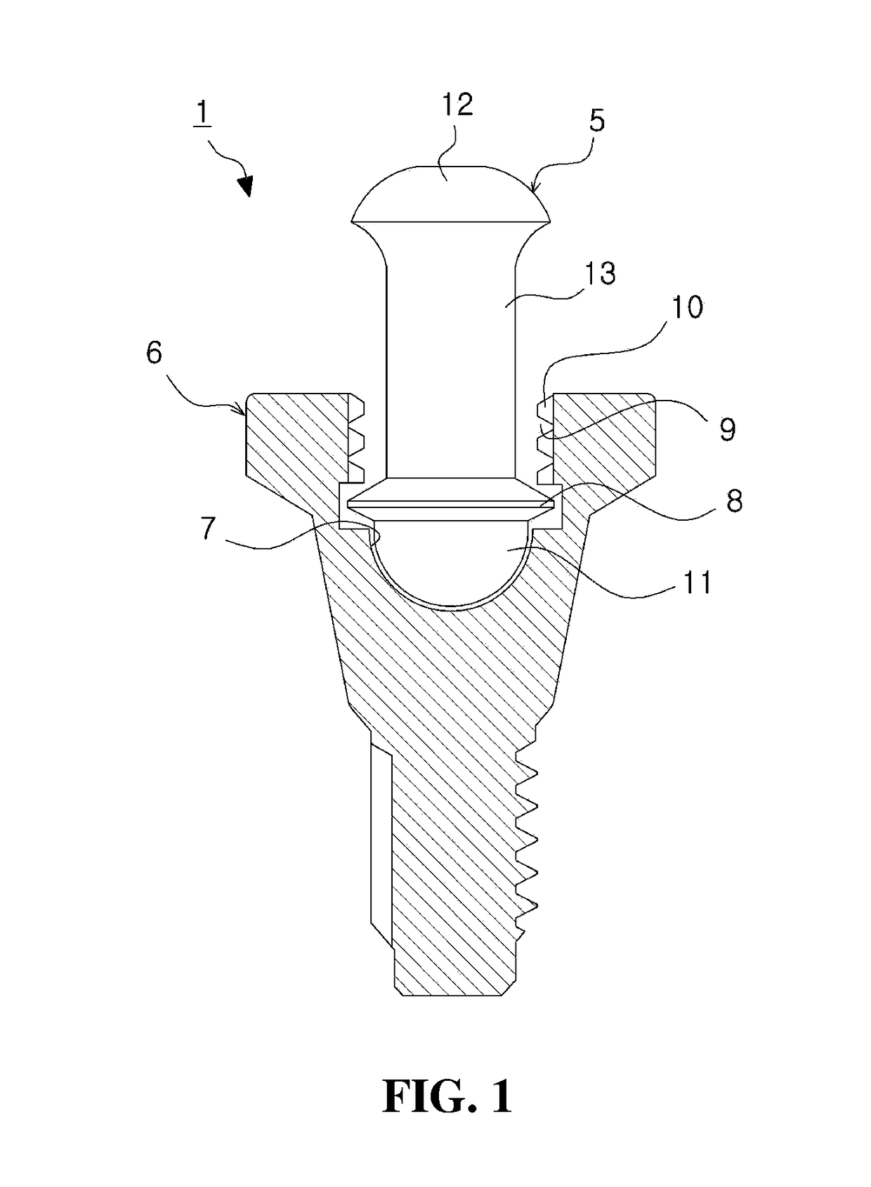
[0031]Hereinafter, a denture-fixing attachment according to a preferred embodiment of the present invention will be described in detail with reference to the attached drawings.

[0032]The present invention may, however, be embodied in different forms and should not be construed as limited to the embodiments set forth herein. Rather, these embodiments are provided so that this disclosure will be thorough and complete, and will fully convey the scope of the present invention to those skilled in the art. In the drawings, the shapes of components are exaggerated for clarity of illustration. In the drawings, the same or similar elements are denoted by the same reference numerals even though they are depicted in different drawings. In the following description, a detailed description of known functions and configurations incorporated herein will be omitted when it may make the subject matter of the present invention rather unclear.

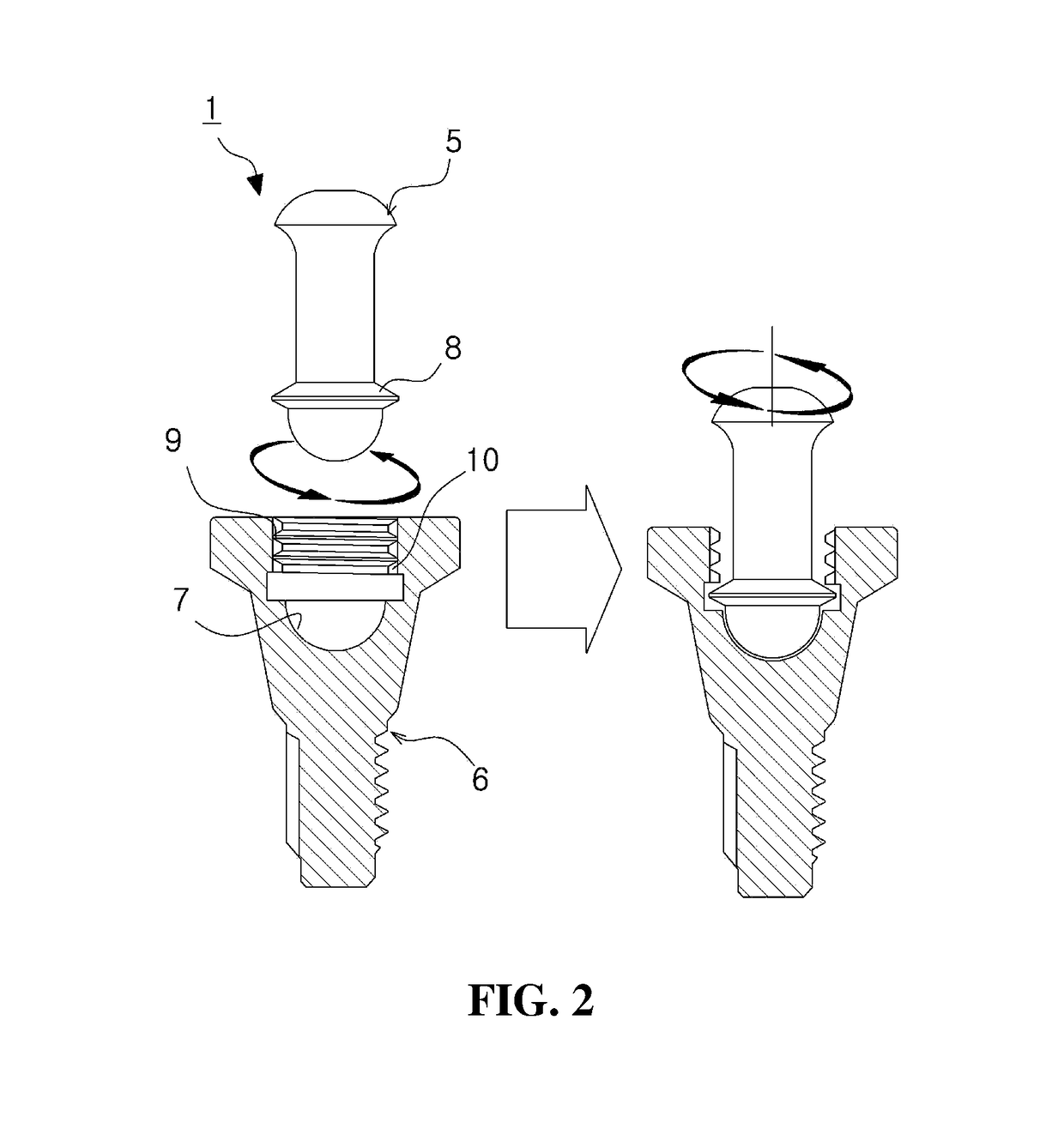
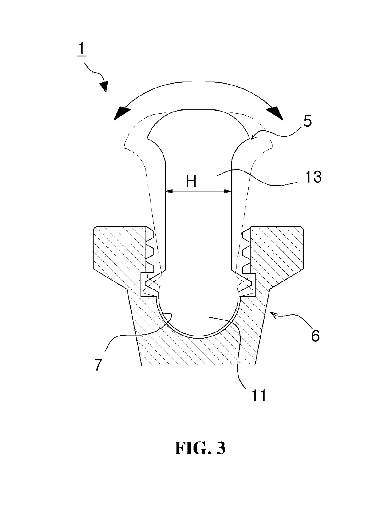
[0033]FIGS. 2 to 4 are views showing a denture-fixing attach...


PUM


Abstract

Provided is a denture fixing attachment including: a rod-shaped joint member, having an upper end for supporting a denture fixed thereto and a locking protruding portion protruding laterally from a lower portion of the joint member; and an abutment having a coupling portion formed in an outer surface of a lower portion thereof so as to be coupled to a fixture recess formed in the fixture, and a receiving portion formed in an upper portion thereof so as to receive the lower portion of the joint member therein, wherein the receiving portion of the abutment includes a receiving recess for receiving the lower portion of the joint member inserted thereinto, and a stop protruding portion provided in the receiving portion above the receiving recess and having a guide groove disposed adjacent to the stop protruding portion for guiding coupling movement of the locking protruding portion fitted thereinto.

Description

[0001]The present application is a U.S. national stage application of PCT / KR2015 / 001053 filed on Feb. 2, 2015 designating the United States, and claims foreign priority to Korean Application KR10-2014-0026568 filed on Mar. 6, 2014.TECHNICAL FIELD[0002]The present invention relates to a denture-fixing attachment used to fix a denture after a dental implant treatment and, more particularly, to a denture-fixing attachment, which has an economic effect due to a simple structure and consequent improvement in productivity, highly efficient workability due to a simplified assembly process, and increased stability in use due to the secure maintenance of engagement force for a long time period and consequent prevention of unexpected release of engagement.BACKGROUND OF THE INVENTION[0003]Conventionally, when a tooth is pulled out, a false tooth is positioned in place of the pulled-out tooth, or a dental bridge treatment, in which surrounding teeth are employed as pillars and a crown is positi...

Claims


Application Information

Patent Timeline
Patent Type & Authority Patents(United States)
IPC IPC(8): A61C8/00
CPCA61C8/0053A61C8/0095A61C8/0062A61C8/0048A61C8/00A61C13/00
Inventor WANG, JE WON
Owner WANG JE WON
Why Eureka
Try Eureka