

Constant velocity universal joint
a universal joint and constant velocity technology, applied in the direction of yielding couplings, couplings, rotary machine parts, etc., can solve the problems of increasing the induced thrust, the design limitation of prohibiting greater operating angles, and so as to improve the fatigue life of the contact surface, suppress the fluctuation of load points, and enhance the fatigue strength
- Summary
- Abstract
- Description
- Claims
- Application Information
AI Technical Summary
Benefits of technology
Problems solved by technology
Method used
Image

Examples
first embodiment
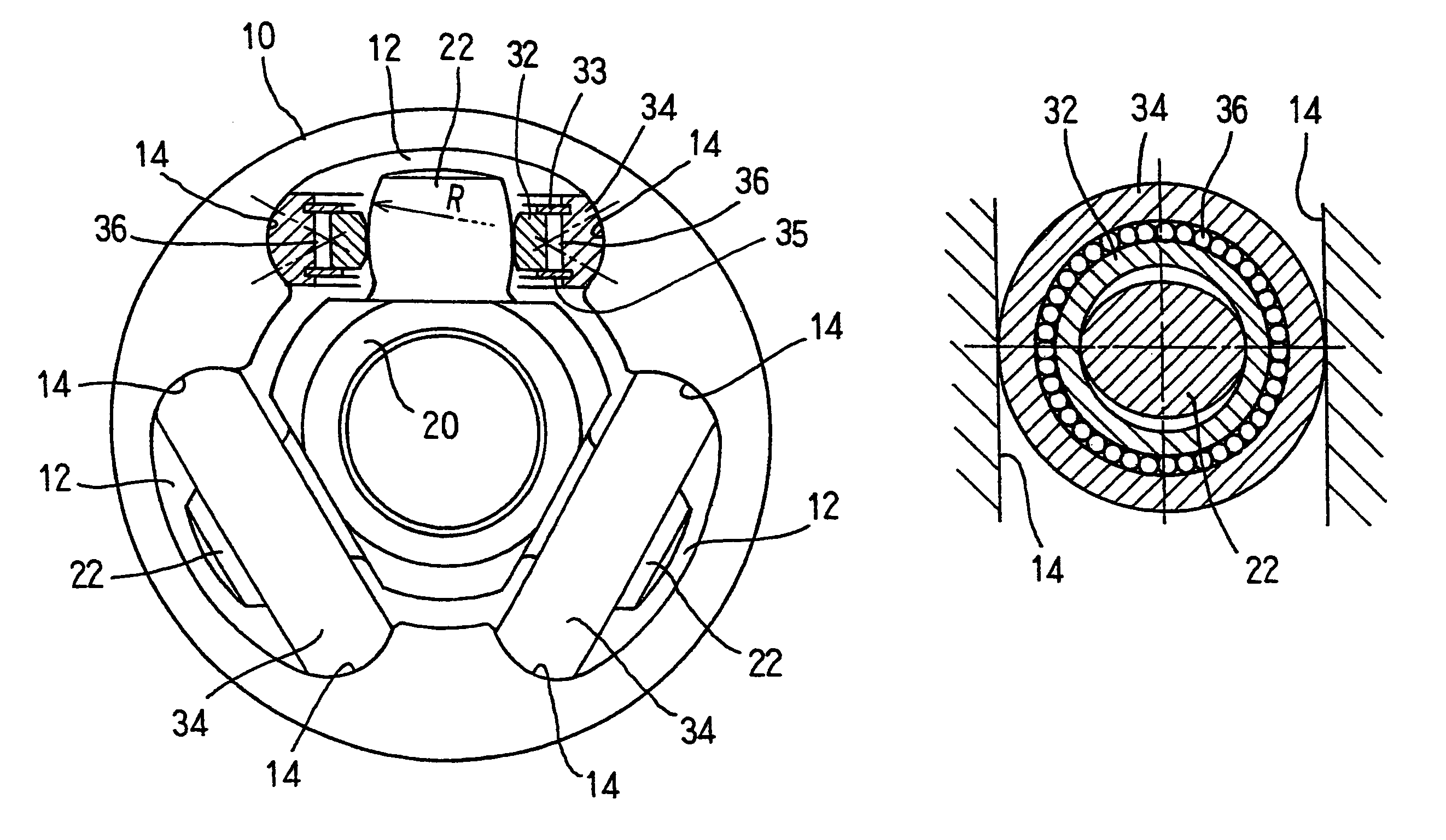
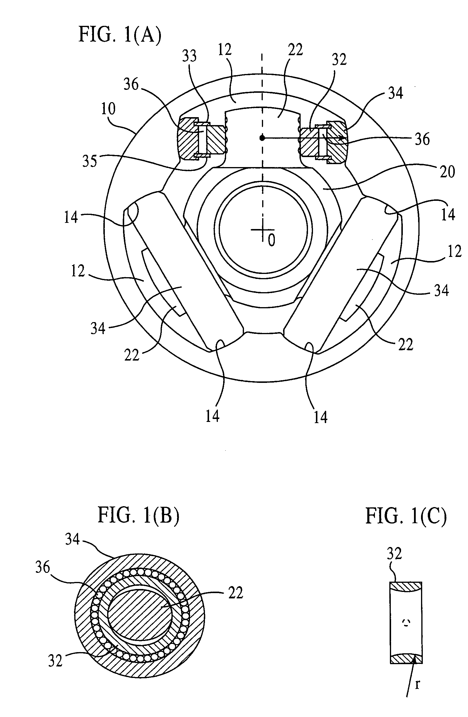
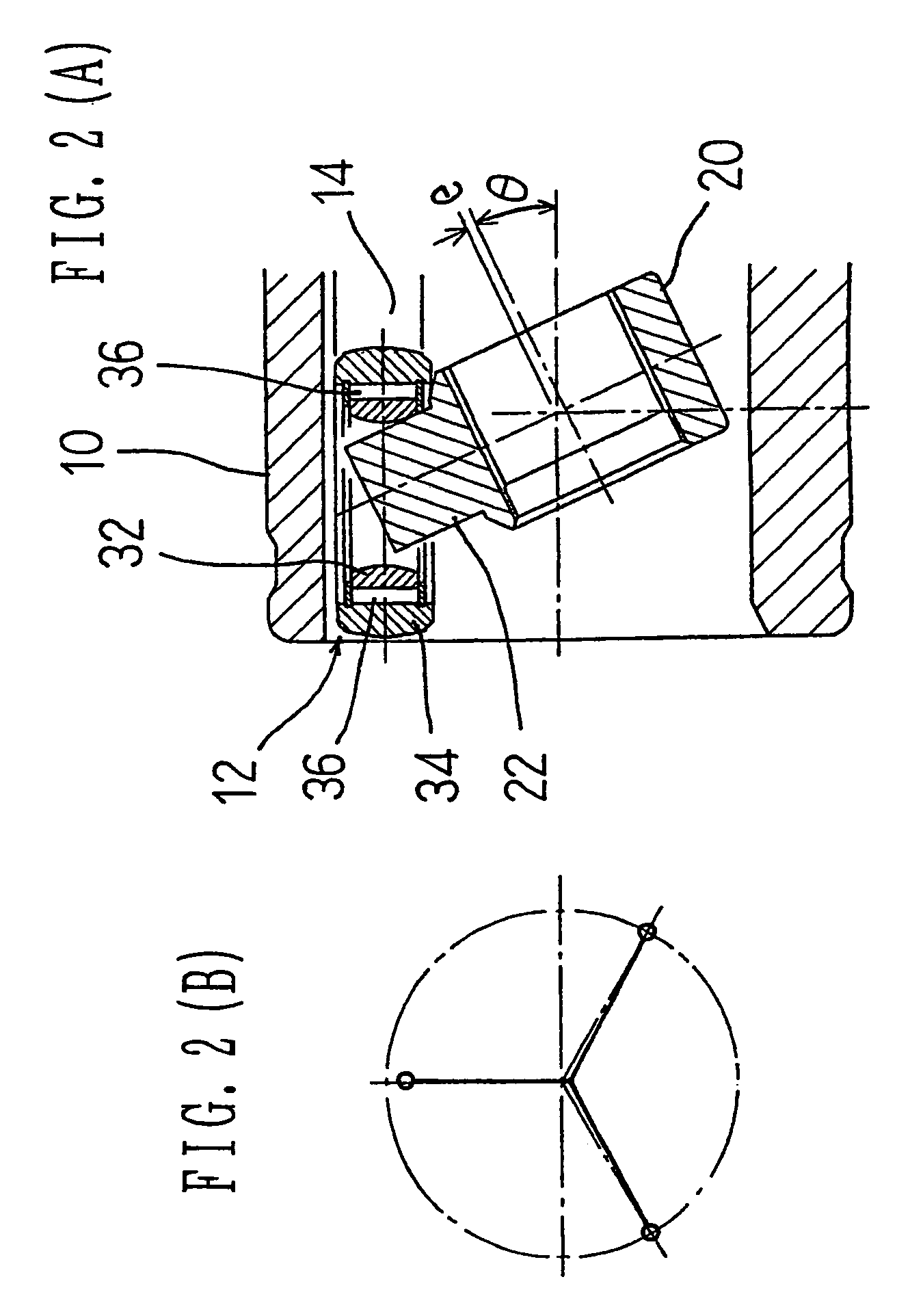
[0129]FIGS. 1(A) through 2(B) shows a tripod type constant velocity universal joint according to the present invention. FIG. 1(A) shows an end face of the joint (partially sectioned), and FIG. 2(A) shows a longitudinal section of the joint at an operating angle of θ. The constant velocity universal joint is chiefly composed of an outer joint member 10 and a tripod member 20. The outer joint member 10 is connected to one of two shafts to be coupled, and the tripod member 20 is to the other.
[0130]The outer joint member 10 has three track grooves 12 axially extending in its inner periphery. Each of the track grooves 12 has roller guideways 14 formed on its circumferentially-opposed side walls. The tripod member 20 has three trunnions 22 projecting radially. Each of the trunnions 22 carries a roller 34, and this roller 34 is accommodated in one of the track grooves 12 in the outer joint member 10. In each track groove 12, the roller guideways 14 opposed to each other in the circumferent...
second embodiment
[0145]FIGS. 8(A) through 9(B) show a tripod type constant velocity universal joint according to the present invention. Here, FIG. 8(A) is an end view of the joint (partially sectioned). FIG. 8(B) shows a section perpendicular to a trunnion. FIG. 9(A) shows a longitudinal section of the joint at an operating angle of θ. The constant velocity universal joint is chiefly composed of an outer joint member 10 and a tripod member 20. The outer joint member 10 is connected to one of two shafts to be coupled, and the tripod member 20 is connected to the other.
[0146]As shown in FIGS. 8(A) and 8(B), the outer joint member 10 has three track grooves 12 axially extending in its inner periphery. Each of the track grooves 12 has roller guideways 14 formed on its circumferentially-opposed side walls. The tripod member 20 has three trunnions 22 projecting radially. A roller 34 is attached to each of the trunnions 22, and this roller 34 is accommodated in one of the track grooves 12 in the outer join...
fourth embodiment
[0166]FIGS. 18(A) through 19(B) show a tripod type constant velocity universal joint according to the present invention. FIG. 18(A) shows a cross section of the joint, FIG. 18(B) a section perpendicular to a trunnion, and FIG. 18(C) a section of a support ring. FIG. 19(A) shows a longitudinal section of the joint with an operating angle (θ).
[0167]As shown in FIGS. 18(A)–18(C), the constant velocity universal joint is chiefly composed of an outer joint member 10 and a tripod member 20. The outer joint member 10 is connected to one of two shafts to be coupled, and the tripod member 20 is connected to the other.
[0168]The outer joint member 10 has three track grooves 12 axially extending in its inner periphery. Each of the track grooves 12 has roller guideways 14 formed on its circumferentially-opposed side walls. The tripod member 20 has three trunnions 22 projecting radially. A roller 34 is attached to each of the trunnions 22, and this roller 34 is accommodated in one of the track gr...
PUM
 Abstract
Description
Claims
Application Information