

Medical device with deflecting shaft and related methods of manufacture and use
a technology of medical devices and shafts, which is applied in the direction of manufacturing tools, surgical forceps, applications, etc., can solve the problems of difficult manipulation, inability to access certain tissues with a given surgical device, and limited manipulation of the endoscop
- Summary
- Abstract
- Description
- Claims
- Application Information
AI Technical Summary
Benefits of technology
Problems solved by technology
Method used
Image

Examples
Embodiment Construction
[0001]1. Field of the Invention
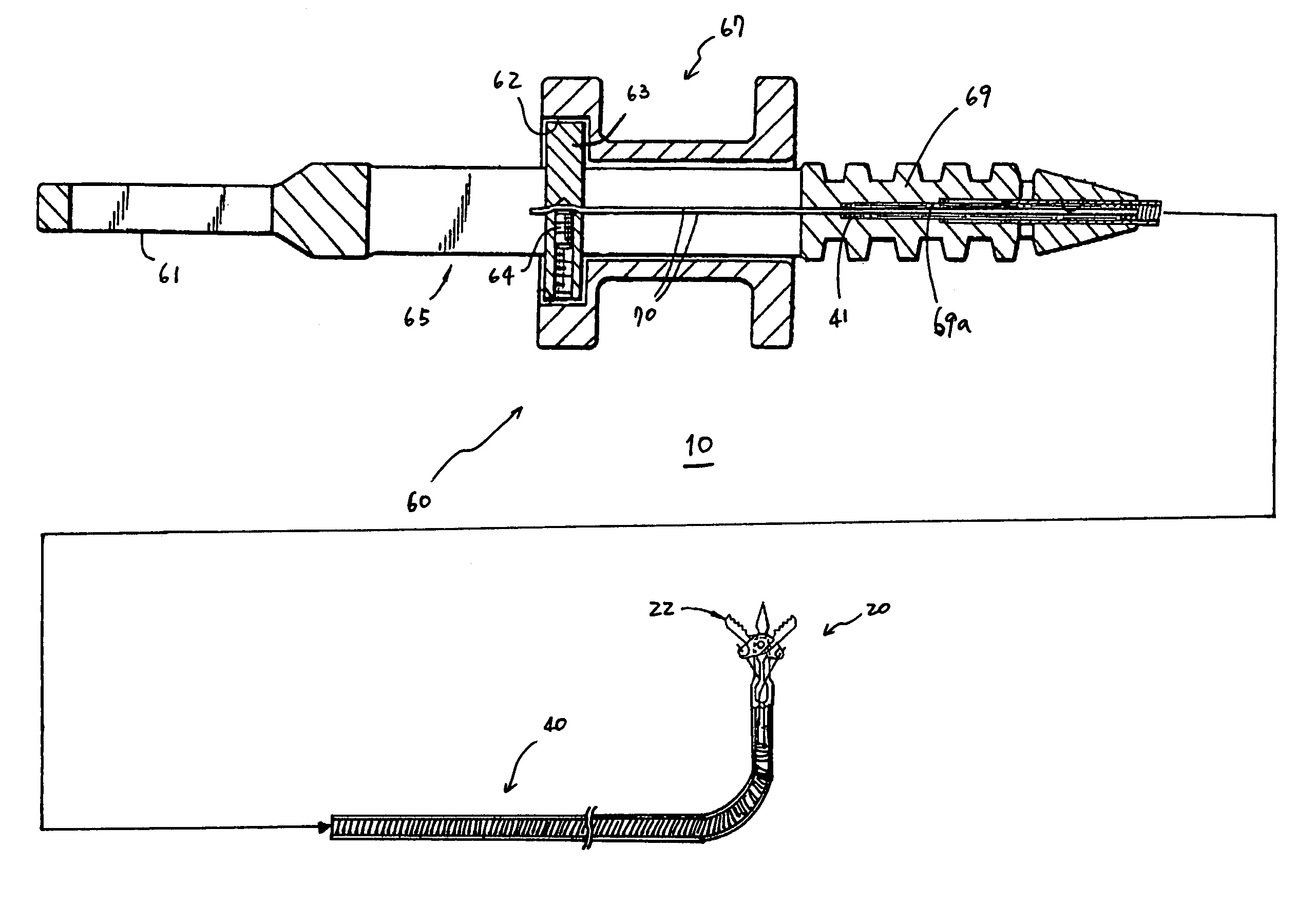
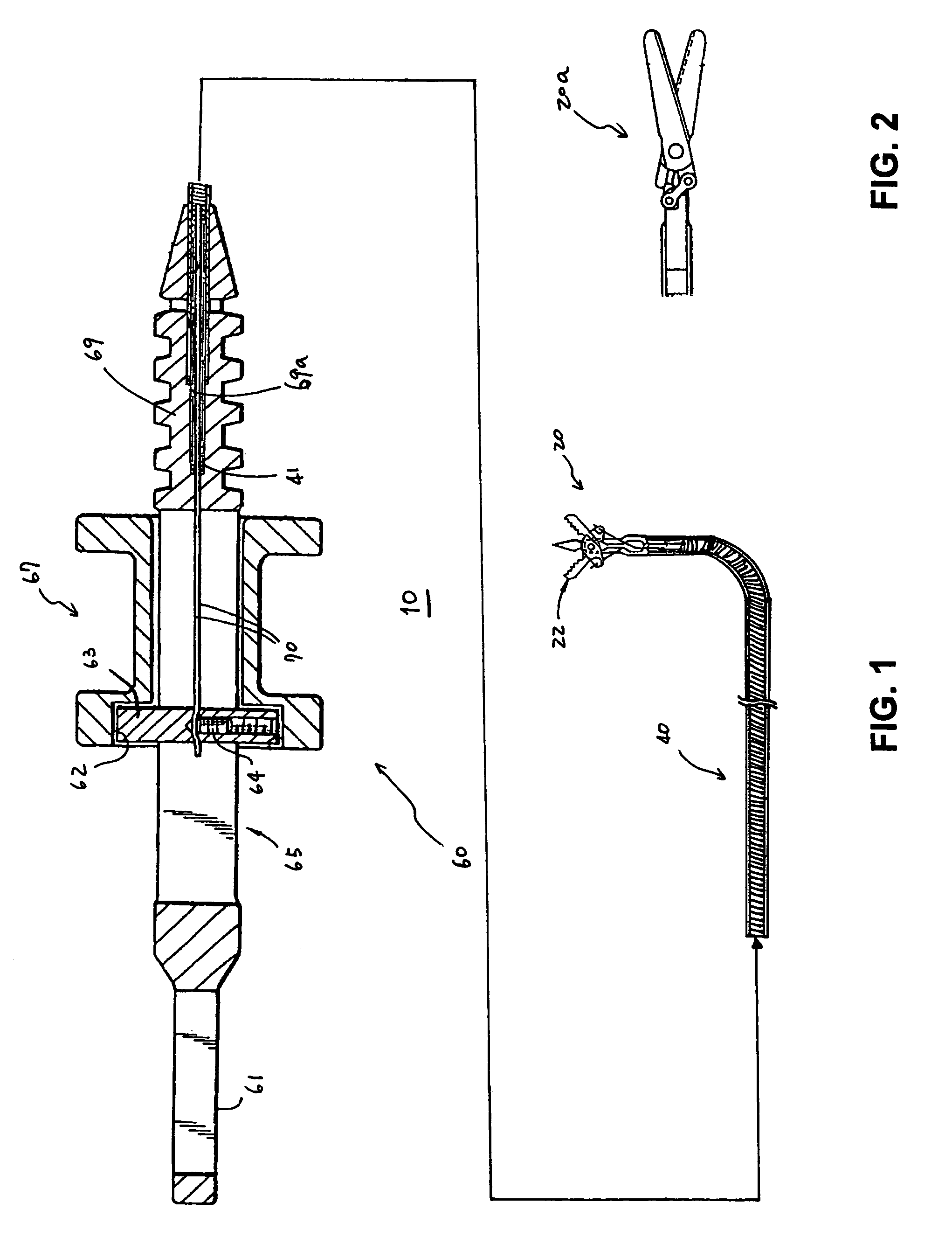
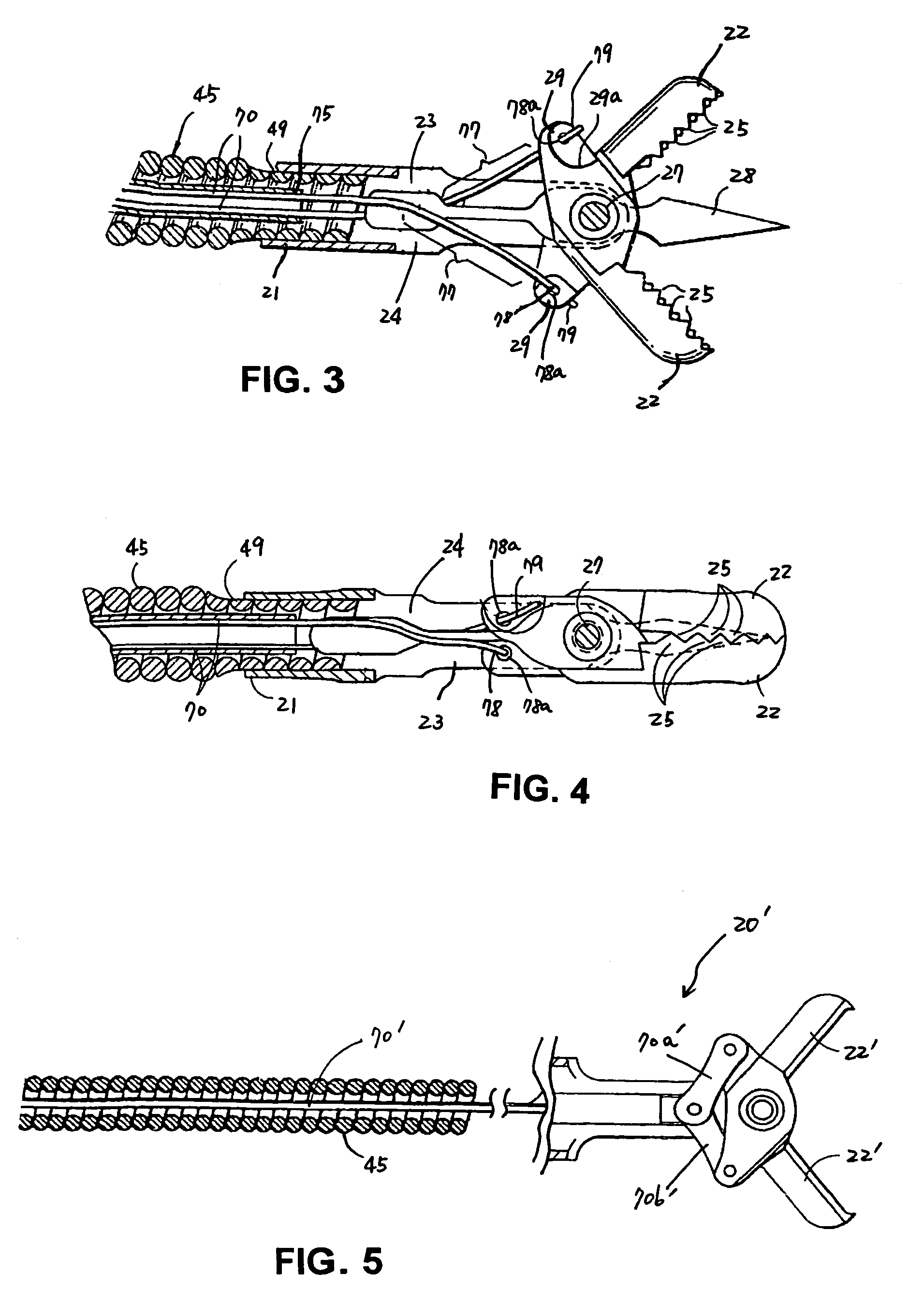
[0002]Embodiments of the invention relate to medical devices having deflecting shafts and related methods thereof. In a particular embodiment, the invention relates to a shaft having a deflectable distal portion for use with an end effector assembly that performs a medical procedure.
[0003]2. Description of the Related Art
[0004]A number of different types of medical devices are being used to access tissue sites within a patient's body. For example, in a surgical procedure involving severing of tissue within a patient's body, a suitable tissue cutting device, such as, for example, biopsy forceps, a snare, or scissors, may be used, typically in conjunction with endoscopic assistance. Such a tissue acquisition device may include an elongated, tubular control shaft, made of, for example, a wire coil, through which one or more actuation wires pass. This shaft generally requires sufficient flexibility to allow advancement of the device through a tortuous body...
PUM
| Property | Measurement | Unit |
|---|---|---|
| length | aaaaa | aaaaa |
| length | aaaaa | aaaaa |
| length | aaaaa | aaaaa |
Abstract
Description
Claims
Application Information