
Capping layer for enhanced performance media

a technology of enhanced performance and cladding layer, which is applied in the field of thermal writing of high density data media, can solve the problems of affecting the ability to write and erase data bits on the media, introducing imperfections in the media, and limiting the ability of electron beams to penetrate through relatively thick cladding layers, etc., and achieves the effect of robust high melting point material

Inactive Publication Date: 2006-05-30
HEWLETT PACKARD DEV CO LP
View PDF2 Cites 11 Cited by
  • Summary
  • Abstract
  • Description
  • Claims
  • Application Information

AI Technical Summary

Benefits of technology

The present invention provides a data storage and retrieval medium that can be altered by an energy beam and has a separate capping layer that is transparent to the energy beam. The capping layer comprises at least one material from a group comprising a robust high melting point material, an electrically conducting material, a thin dielectric layer, and an epitaxial material. The technical effects of this invention include improved data storage and retrieval using a more robust and reliable medium that can withstand energy beam alteration. Additionally, the invention provides a method for fabricating the data storage and retrieval medium using a variety of materials and techniques.

Problems solved by technology

In this setting, ablation of the phase change medium or chemical changes introduced to the medium can be highly undesirable, and may introduce imperfections in the media and / or impede the ability to write and erase data bits on the media.
First, near-field writing requires that the optical probe pass within much less than one wavelength of the media surface, which is generally incompatible with typical ZnS—SiO2 cladding thicknesses employed, as well as being incompatible with the polycarbonate used to cover the media.
In electron beam thermal writing, electron beams typically cannot penetrate through relatively thick cladding layers unless extremely high beam energies are employed, which is impractical.
Furthermore, thick insulating cladding layers tend to charge and deflect the electron beam, which is also undesirable.
The problems of ablation and chemical modification of the data layer remain, however, in the presence of near-field optical and electron beam thermal recording schemes.

Method used


Image

  • Capping layer for enhanced performance media
  • Capping layer for enhanced performance media
  • Capping layer for enhanced performance media

Examples


Embodiment Construction

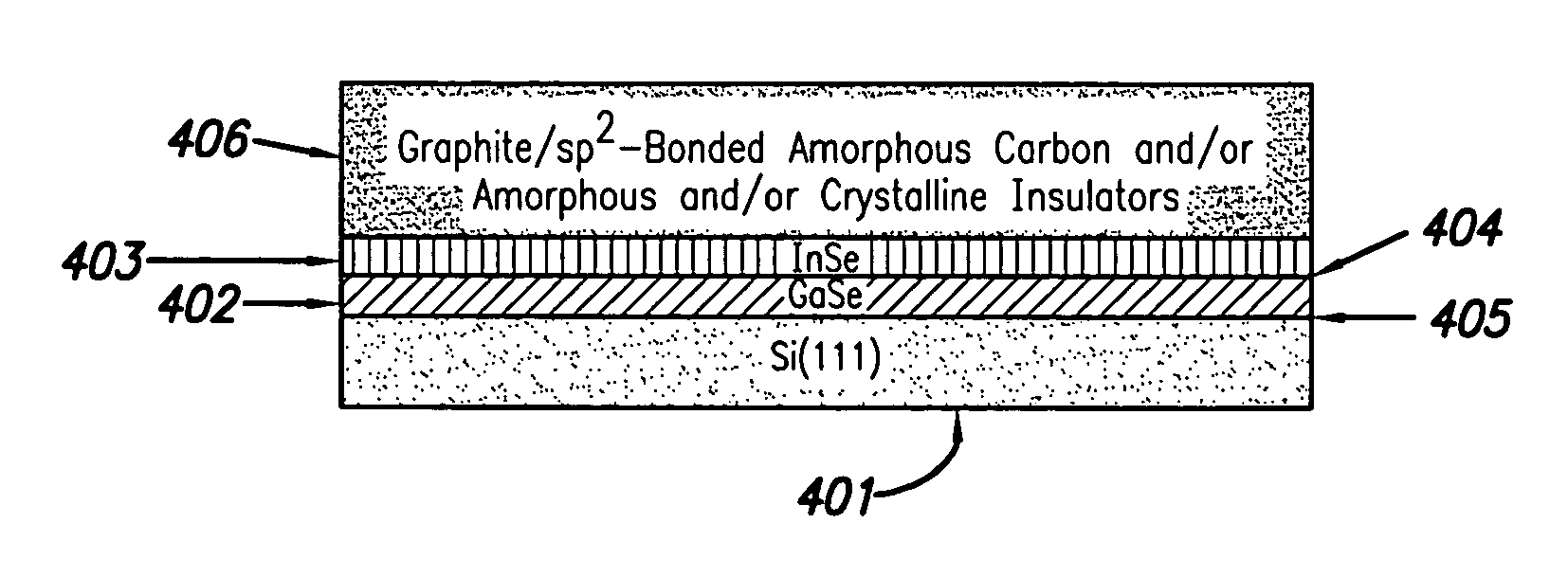
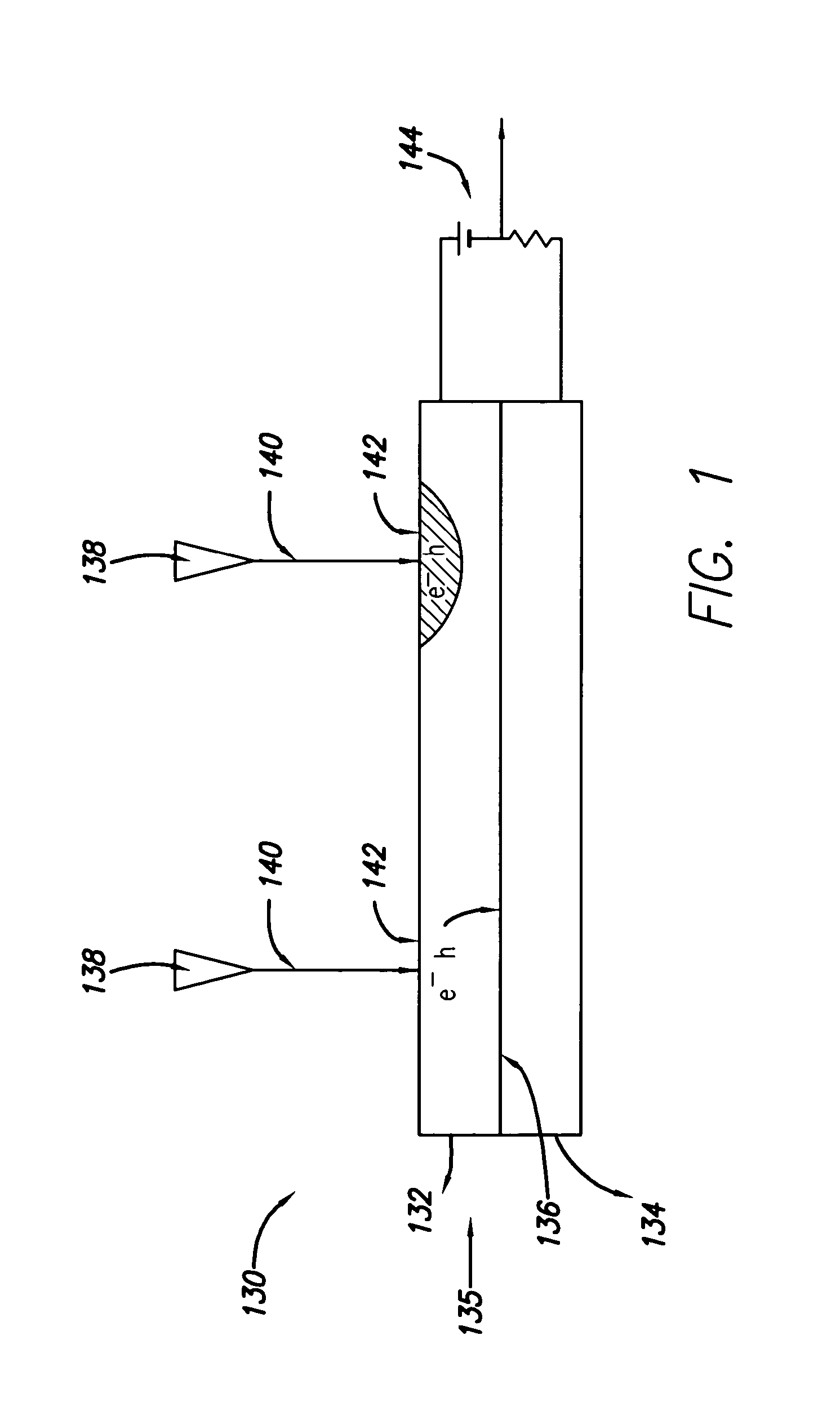
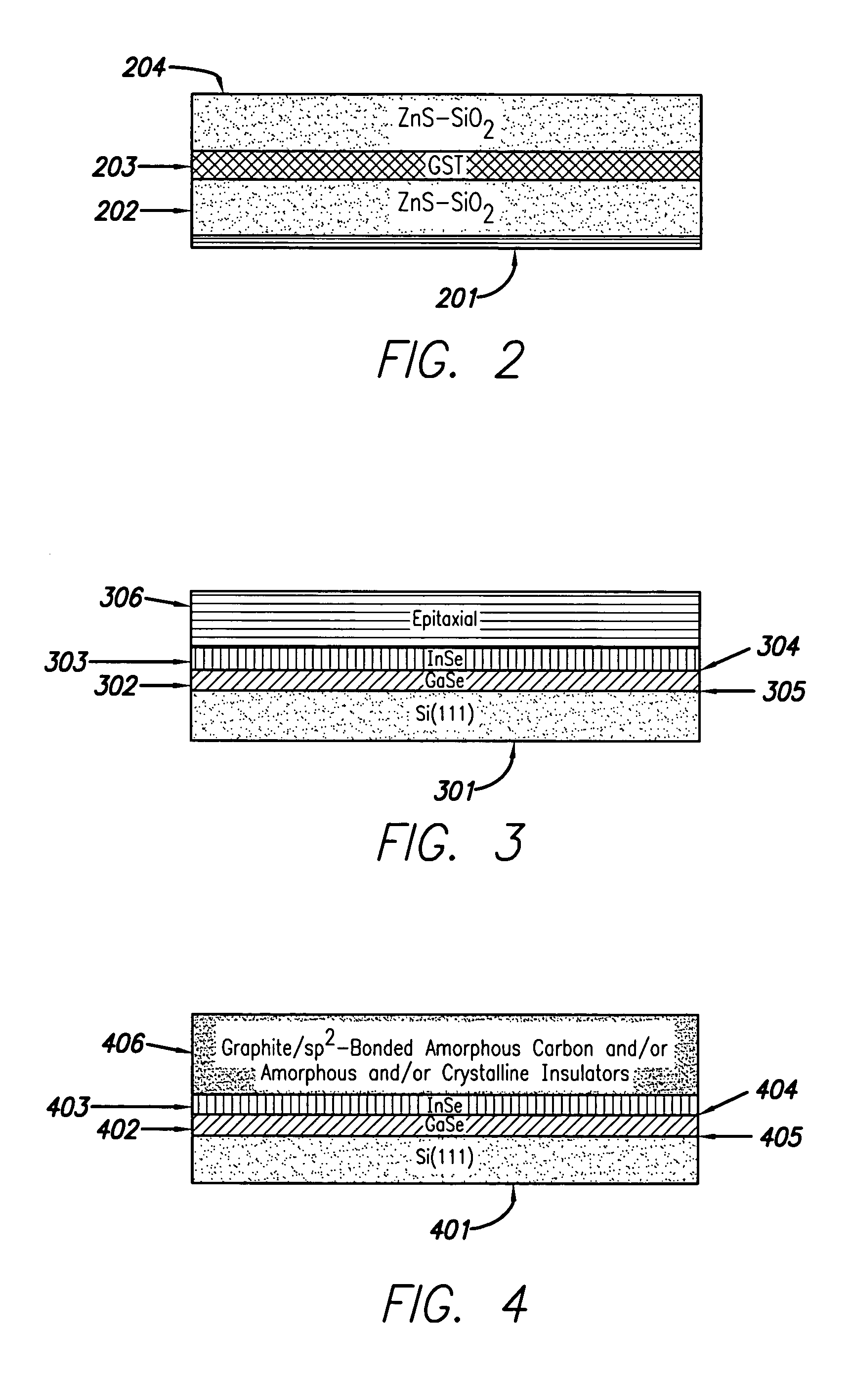
[0022]The present design includes various capping layers employing different materials wherein use of these materials tends to increase the overall effectiveness of writing to and reading from the media in the presence of near-field and electron beam recording devices. As used herein, the term “materials” includes all kinds and types of compounds, alloys and other combinations of elements. Also, as used herein, the terms “cladding layer” and “capping layer” are used interchangeably, and both terms indicate the topmost or outermost layers of the stack above or away from the base layers. Further, as used herein, the term “data layer” may be construed to mean multiple physical layers of similar or varying materials. In practice, a “data layer” may in many cases include multiple thin film layers composed of differing materials.

[0023]Different forms of data storage and retrieval devices include, for example, photodiodes and cathododiodes, phototransistors and cathodotransistors, photocon...


PUM

PropertyMeasurementUnit
atomic numberaaaaaaaaaa
mass densityaaaaaaaaaa

Abstract

A media storage device and method for fabricating said device is provided. The device comprises a data layer capable of storing and erasing data via application of an energy beam, such as a near field optical non diffraction limited beam or electron beam. A separate capping layer is deposited on the data layer. The separate capping layer is relatively transparent to the energy beam and may be formed from various materials, including but not limited to an epitaxial material, a conducting material, and a robust high melting point material, such as Molybdenum.

Description

BACKGROUND OF THE INVENTION[0001]1. Field of the Invention[0002]The present invention relates generally to the field of thermal writing of high density data media, and more particularly to the specific composition and methods of forming high density data recording products for use in near-field optical and electron beam writing.[0003]2. Description of the Related Art[0004]Phase-change media are a widely available means for providing high density data storage, and such media may include CD-RW, DVD-RAM, and DVD-RW formats, among others. In this type of media, data is stored at a particular location, typically micron sized, and storage and erasure occurs based on the microstructure of the target region. Microstructures are either crystalline or amorphous. Bit writing in crystalline media requires melting the desired region and then rapidly quenching the region to a glassy state. Bit erasure involves transitioning from this glassy state using relatively slow, gentle heating to produce r...

Claims


Application Information

Patent Timeline
Patent Type & Authority Patents(United States)
IPC IPC(8): B32B3/02G11B9/10G11B7/243G11B7/257G11B9/00G11B9/08G11B9/14
CPCB82Y10/00G11B7/257G11B9/10G11B9/14G11B9/1472G11B9/1463G11B7/2532Y10T428/21G11B2007/2431G11B2007/24316G11B2007/25708G11B2007/2571
Inventor CHAIKEN, ALISONGIBSON, GARY
Owner HEWLETT PACKARD DEV CO LP
Learn More