Radiographic apparatus

a radiographic apparatus and apparatus technology, applied in the field of radiographic apparatus, can solve the problems of difficult handling, lack of rigidity, and complicating the structure of the apparatus, and achieve the effect of reducing backscattering and holding down the weight of the radiographic apparatus

Inactive Publication Date: 2006-05-30
CANON KK
View PDF16 Cites 3 Cited by
  • Summary
  • Abstract
  • Description
  • Claims
  • Application Information

AI Technical Summary

Benefits of technology

[0018]The present invention has been made in consideration of the above-described situation, and has as its object to p

Problems solved by technology

However, compared to other metals, lead lacks rigidity and is hard to handle, and for these reasons a member is required to support the lead, which complicates the structure of the apparatus.
In particular, with a portable (that is, hand-held) radiographic apparatus (also called an electronic ca

Method used


Image

  • Radiographic apparatus
  • Radiographic apparatus
  • Radiographic apparatus

Examples


first embodiment

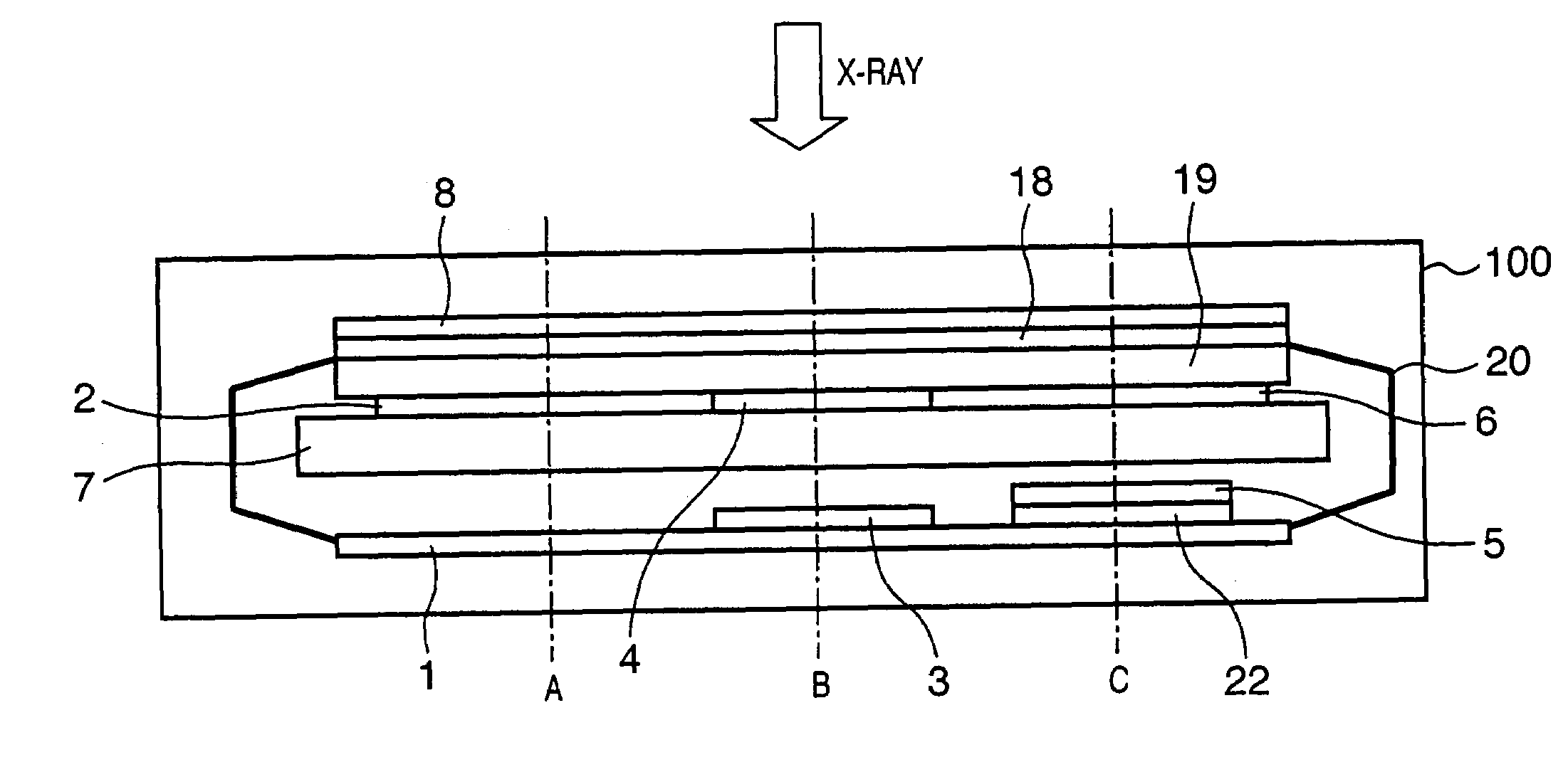
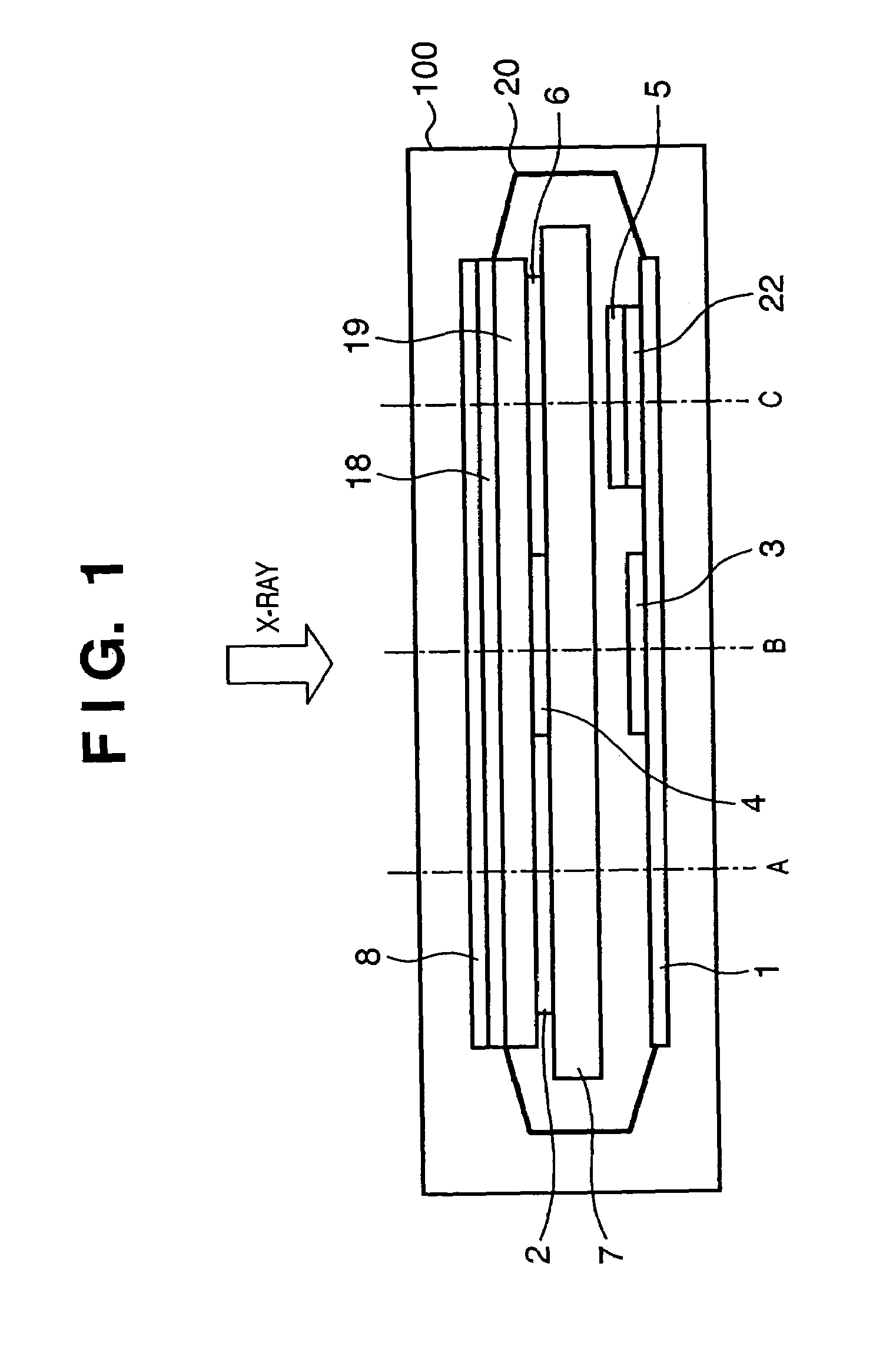
[0030]FIG. 1 is a diagram showing a schematic cross-sectional view of the structure of a radiographic apparatus according to a first embodiment of the present invention. It should be noted that constituent elements that are the same as those of the apparatus described in FIGS. 5–7 are given the same reference numbers, and a description thereof is omitted.

[0031]What is different from that shown in FIG. 6 is that an X-ray shield member using material that differs depending on the area is used instead of the X-ray shield member 21. In the example shown in FIG. 1, X-ray shield members 2, 4 and 6 are provided in areas disposed opposite the electrical circuit board 1, element 3 and protective layer 5, with the material of the X-ray shield members differing according to the positions of the elements. Materials are selected for the X-ray shield members 2, 4 and 6 so that the amount of scattered rays (the amount of backscattering) from the lower layer is approximately uniform.
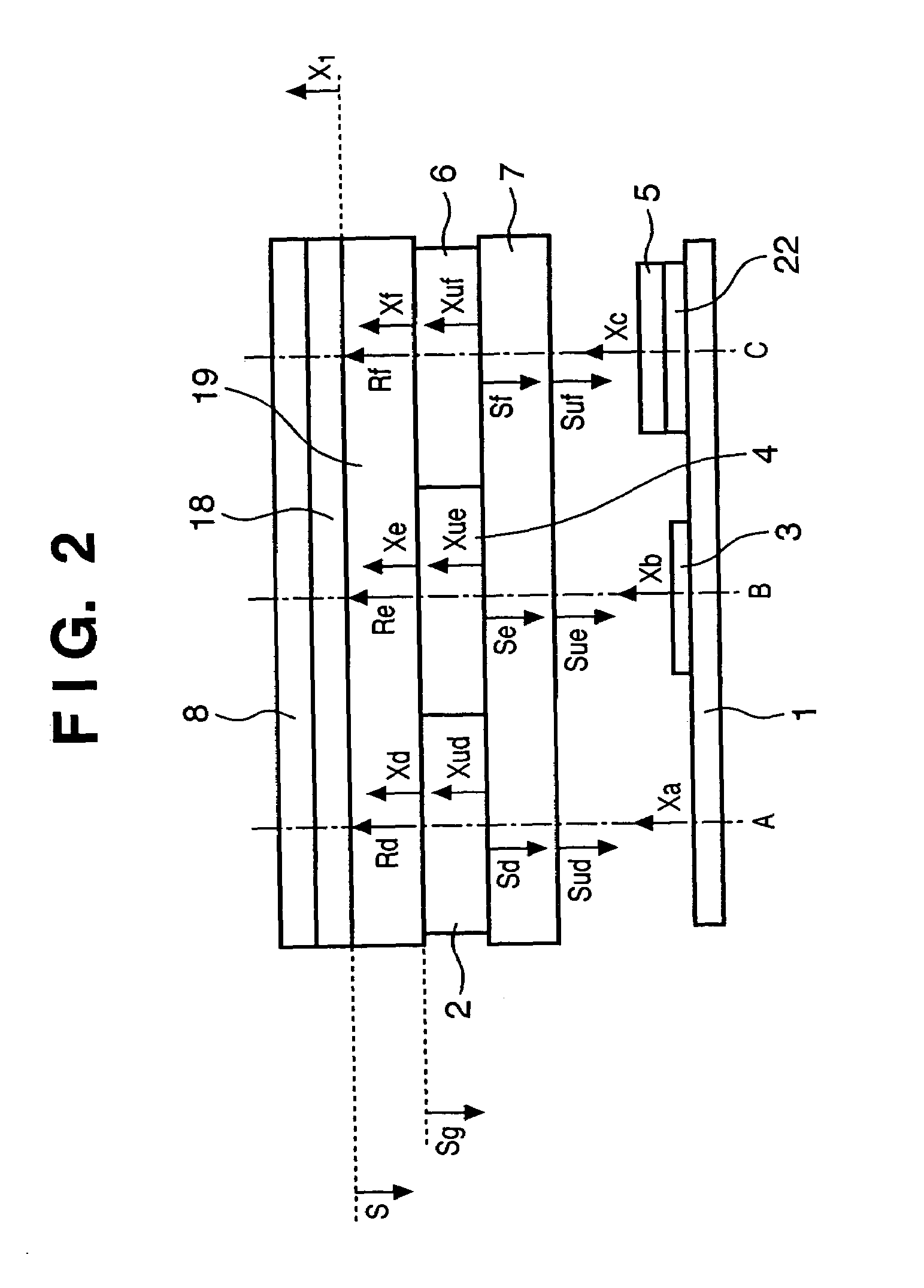
[0032]FIG. 2 is...

second embodiment

[0038]FIG. 3 is a diagram showing a schematic cross-sectional view of the structure of a radiographic apparatus according to a second embodiment of the present invention. It should be noted that constituent elements identical to those described in FIG. 1 are given the same reference numerals, and a description thereof is omitted.

[0039]What is different from FIG. 1 is that the X-ray shield member has different thicknesses depending on the area. Specifically, a thin X-ray shield member 9 is provided for an area A disposed opposite the electrical circuit board 1, a intermediate X-ray shield member 10 is provided for an area B disposed opposite the element 3, and a thick X-ray shield member 11 is provided for an area C disposed opposite the protective layer 5, thus changing the thickness of the X-ray shield members depending on the disposition of the elements. The thickness of each of the X-ray shield members 9, 10 and 11 is varied so that the amount of scattered rays from the lower lay...


PUM


Abstract

A radiographic apparatus includes photoelectric converter elements for converting a radiographic image of an object into image signals and a shield member for shielding the photoelectric converter elements from scattered rays arising within the radiographic apparatus from radiation passing through the photoelectric converter elements. The shield member has a plurality of areas, in which at least one of a radiation transmittivity and a radiation scattering probability varies.

Description

FIELD OF THE INVENTION[0001]The present invention relates to a radiographic apparatus having an imager that includes a plurality of photoelectric converter elements.BACKGROUND OF THE INVENTION[0002]Conventionally, a method of irradiating an object with radiation and detecting the intensity distribution of the radiation that passes through the object in order to obtain a radiographic image of the object is widely used in industrial non-destructive testing, medical diagnoses and other fields. As a specific example of a typical method of obtaining a radiographic image of an object, there is one that employs a combination of so-called “phosphor sheets” (or intensifying paper), which emits fluorescent light when exposed to radiation, and silver-halide film, in which radiation passing through the object is converted into visible light by the phosphor sheet and the visible light forms a latent image on the silver-halide film, after which the silver-halide film is chemically processed in or...

Claims


Application Information

Patent Timeline
IPC IPC(8): G01T1/24G01T1/20A61B6/00A61B6/06G01N23/04G01T7/00G03B42/02
CPCG01N23/04A61B6/06
Inventor YAMAMOTO, OSAMU
Owner CANON KK
Why Eureka
Try Eureka