Imaging systems and methods for recovering object visibility

a technology of image recovery and object visibility, applied in the field of image recovery systems and methods for photographing objects, can solve the problems of unpredictability of natural illumination, inability to achieve the effect of natural illumination, reducing backscatter, and improving underwater visibility

Active Publication Date: 2013-01-08
TECHNION RES & DEV FOUND LTD
View PDF11 Cites 8 Cited by
  • Summary
  • Abstract
  • Description
  • Claims
  • Application Information

AI Technical Summary

Benefits of technology

[0004]To counter the problems, the present invention looks at widefield (not scanning) illumination with a small (or no) baseline, where the backscatter is modulated by polarization. Preliminary studies by others [G. C. Giakos. Active backscattered optical polarimetric imaging of scattered targets. In IEEE Instr. & Measurement Tech. Conf, volume 1, pages 430-432, 2004; G. D. Gilbert and J. C. Pernicka. Improvement of underwater visibility by reduction of backscatter with a circular polarization technique. App. Opt., 6:741-746, 1967; G. D. Lewis, D. L. Jordan, and P. J. Roberts. Backscattering target detection in a turbid medium by polarization discrimination. App. Opt., 38:3937-3944, 1999] indicated that backscatter can be reduced by polarization. However, the present invention goes further. Using post-processing means, it is possible to remove residual backscatter that is not blocked by optical means. Moreover, a rough estimate of the 3D scene structure may be obtained from the acquired frames. The acquisition setup is a simple modification of instruments used routinely in such media: simply mounting two polarizers, one on the light source and another on the camera. The acquisition process is instantaneous, i.e., requiring only two frames, rather than scanning.
[0016]In one embodiment of the present invention, the first frame of the scene is acquired with the polarizer or the polarization analyzer in a polarization state with an approximate minimum or low visible backscatter. In another embodiment of the present invention, the one or more additional frames of the scene are acquired with the polarizer or the polarization analyzer in a polarization state with approximately maximum or high visible backscatter. It is not necessary to use the absolute minimum or maximum backscatter value, but using a relatively low amount and a relatively high amount of backscatter can produce good results.
[0019]The present invention's active illumination system can include at least one of the following for better performance:
[0032]The derived calibration parameters are useful for estimating the distances between objects in the scene. 3D reconstruction of the scene is most effective in short ranges when light still exists in sufficient intensity and the backscatter has not saturated and still varies rapidly.
[0053](iii) applying a fusion technique using each image components to obtain an image with enhanced contrast, color and / or visibility.
[0068](iv) subtracting a portion or all of the second frame from the first frame to receive an enhanced image with improved contrast and brightness range across the field of view.

Problems solved by technology

However, natural light is in general unavailable in relevant scenarios, as in deep water, pipelines, night and biological tissues.
Moreover, natural illumination may change in time unpredictably [Y. Y. Schechner and N. Karpel. Attenuating natural flicker patterns.
This involves a practical difficulty: the illumination is strongly scattered back towards the camera from particles along the line of sight (LOS), creating backscatter, as shown in FIG. 1.
The backscatter overwhelms the signal, causing severe loss of visibility.
However, this is impossible to do in tight environments such as shipwrecks or pipelines.
Moreover, a construction using long strobe arms is cumbersome and less hydrodynamic.
Such sequences may lengthen the overall acquisition time.
Moreover, such systems have the drawback of being very complex and expensive.

Method used


Image

  • Imaging systems and methods for recovering object visibility
  • Imaging systems and methods for recovering object visibility
  • Imaging systems and methods for recovering object visibility

Examples


Embodiment Construction

[0094]In the following detailed description of various embodiments, reference is made to the accompanying drawings that form a part thereof, and in which are shown by way of illustration specific embodiments in which the invention may be practiced. It is understood that other embodiments may be utilized and structural changes may be made without departing from the scope of the present invention.

2. Theoretical Background

2.1 Artificial Illumination

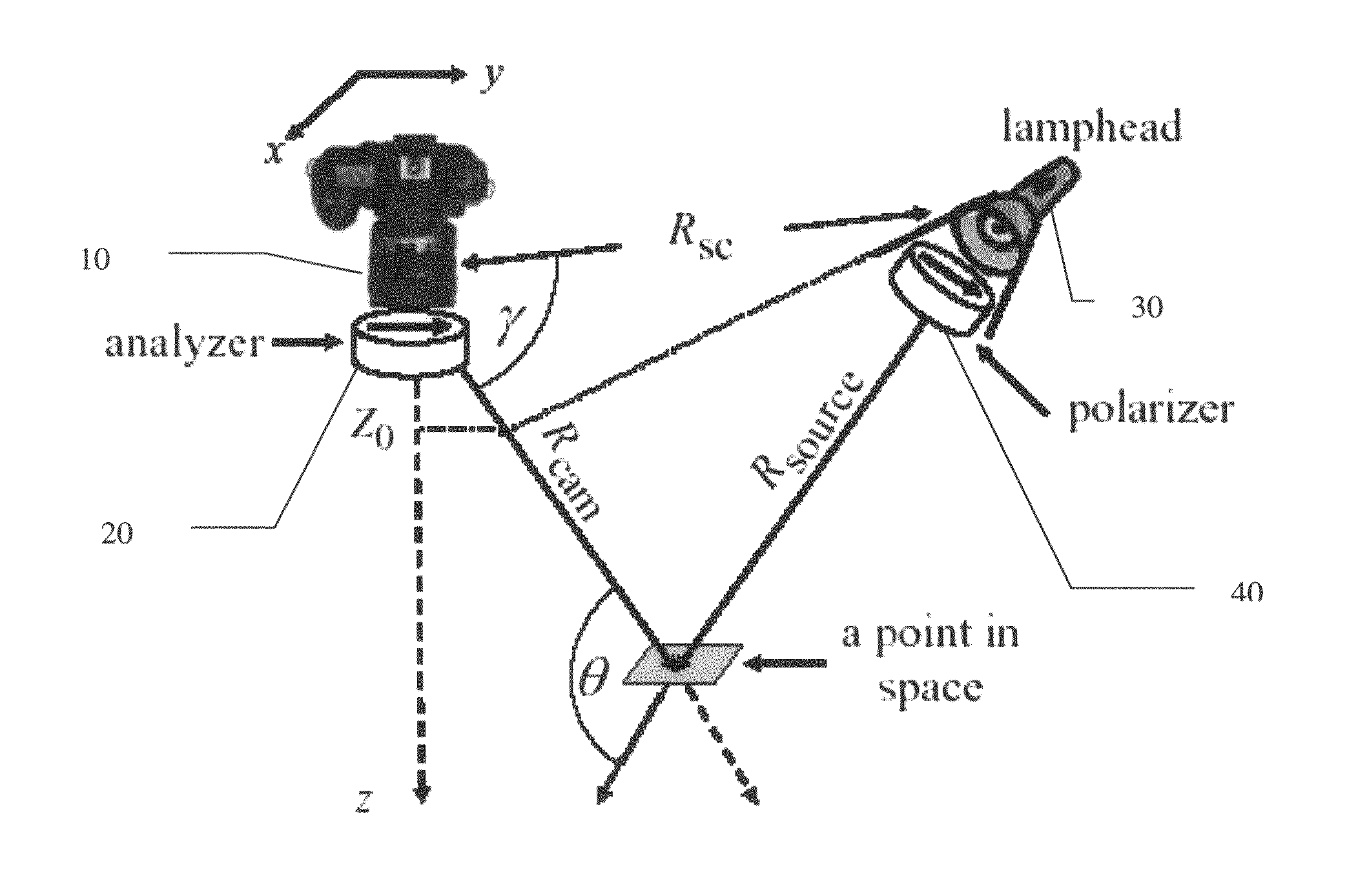
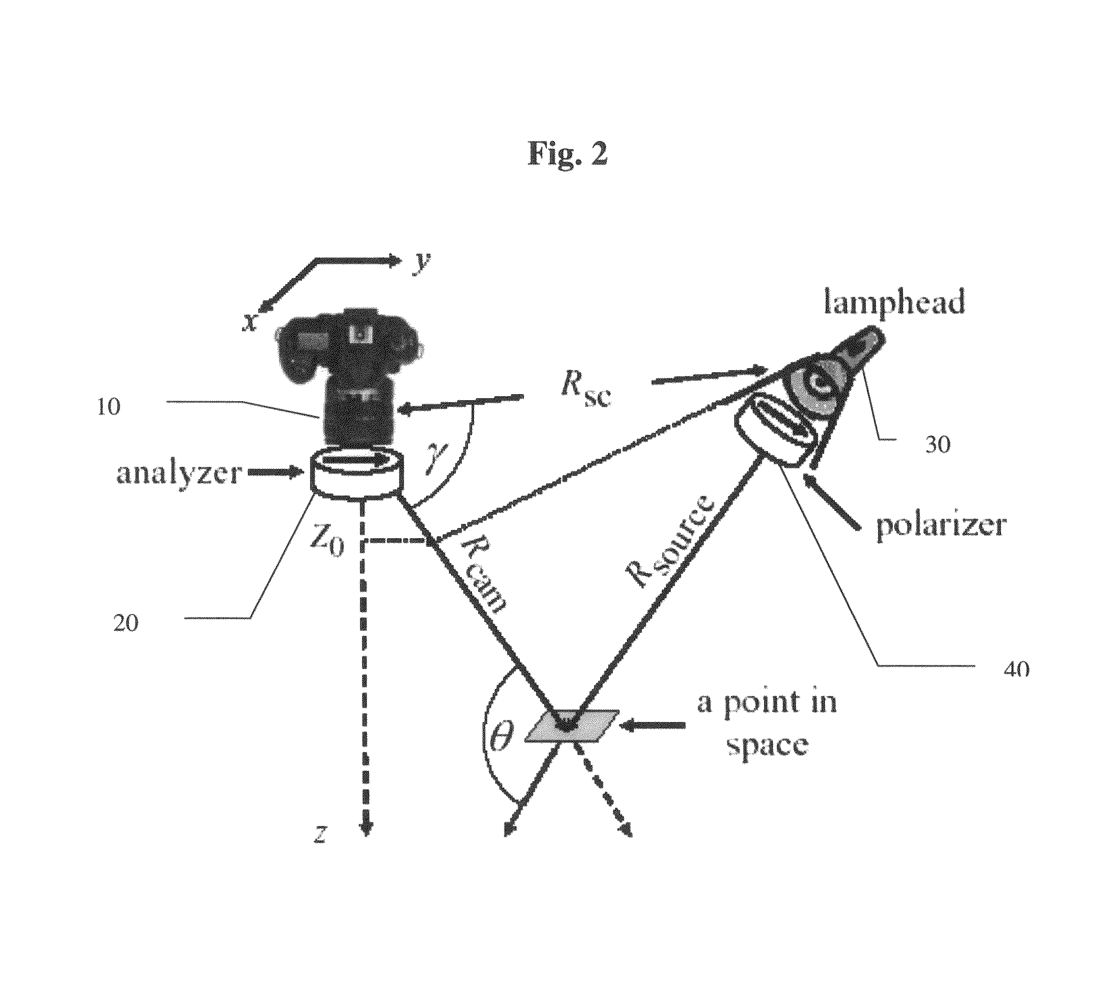
[0095]Consider a camera in a scattering medium. At pixel (x; y), the measured image I(x; y) is the sum of the object signal S(x; y) and a backscatter component B(x; y),

I(x,y)=S(x,y)+B(x,y).  (1)

We now detail these components. Let z be the axial distance from the camera of a point in the volume. This scene point is at a distance Rsource (x, y, z) from a light source which resides by the camera. The source radiance is Lsource. The irradiance of the scene point [J. S. Jaffe. Computer modeling and the design of optimal underwater imaging systems...


PUM


Abstract

A system and method are provided for imaging in scattering media such as fog, water and biological tissues. Normally, such images suffer from poor visibility due to backscattering and signal attenuation. At least two images are taken of the scene using active widefield polarized illumination, with different states of a camera-mounted polarizer. The degree of polarization of backscatter is estimated in every point of the scene, leading to an estimation of the backscatter in every point of the scene. A portion or all of the value of backscatter can be deducted in each point of the scene resulting in an enhanced image with improved contrast and brightness range across the field of view.

Description

CROSS REFERENCE TO RELATED APPLICATIONS[0001]This application is a national stage of international application PCT / IL2007 / 000560, filed 9 May 2007. Additionally, this application claims the benefit of U.S. Provisional Application No. 60 / 798,737, filed 9 May 2006.FIELD OF THE INVENTION[0002]The present invention relates to systems and methods for photographing an object and in particular for photographing an object immersed in a scattering medium such as water, fog or biological tissues.BACKGROUND OF THE INVENTION1. Scattering Media[0003]A wide range of imaging domains exists in scattering media. Several studies [P. C. Y. Chang, J. C. Flitton, K. I. Hopcraft, E. Jakeman, D. L. Jordan, and J. G. Walker. Improving visibility depth in passive underwater imaging by use of polarization. App. Opt., 42:2794-2803, 2003.; E. Namer and Y. Y. Schechner. Advanced visibility improvement based on polarization filtered images. In Proc. SPIE 5888: Polarization Science and Remote Sensing II, pages 36...

Claims


Application Information

Patent Timeline
Patent Type & Authority Patents(United States)
IPC IPC(8): H04N5/222H04N7/00H04N5/253G03B17/08
CPCG06T5/50G06T5/007H04N5/23232G06T2207/30232H04N23/951
Inventor SCHECHNER, YOAVTREIBITZ, TALI
Owner TECHNION RES & DEV FOUND LTD
Why Eureka
Try Eureka