
Time of flight sensor with light baffle system and method

a technology of time-of-flight sensor and light baffle, applied in the direction of optical radiation measurement, pulse technique, instruments, etc., can solve the problems of very sensitive receiving system, very powerful emitting signal, and mechanical constraint that can be very restricting

Active Publication Date: 2022-07-05
DATALOGIC IP TECH
View PDF18 Cites 0 Cited by
  • Summary
  • Abstract
  • Description
  • Claims
  • Application Information

AI Technical Summary

Benefits of technology

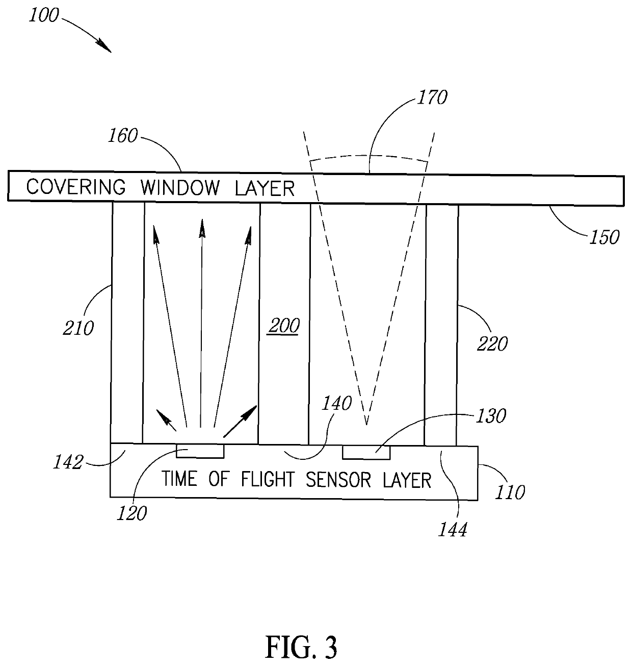
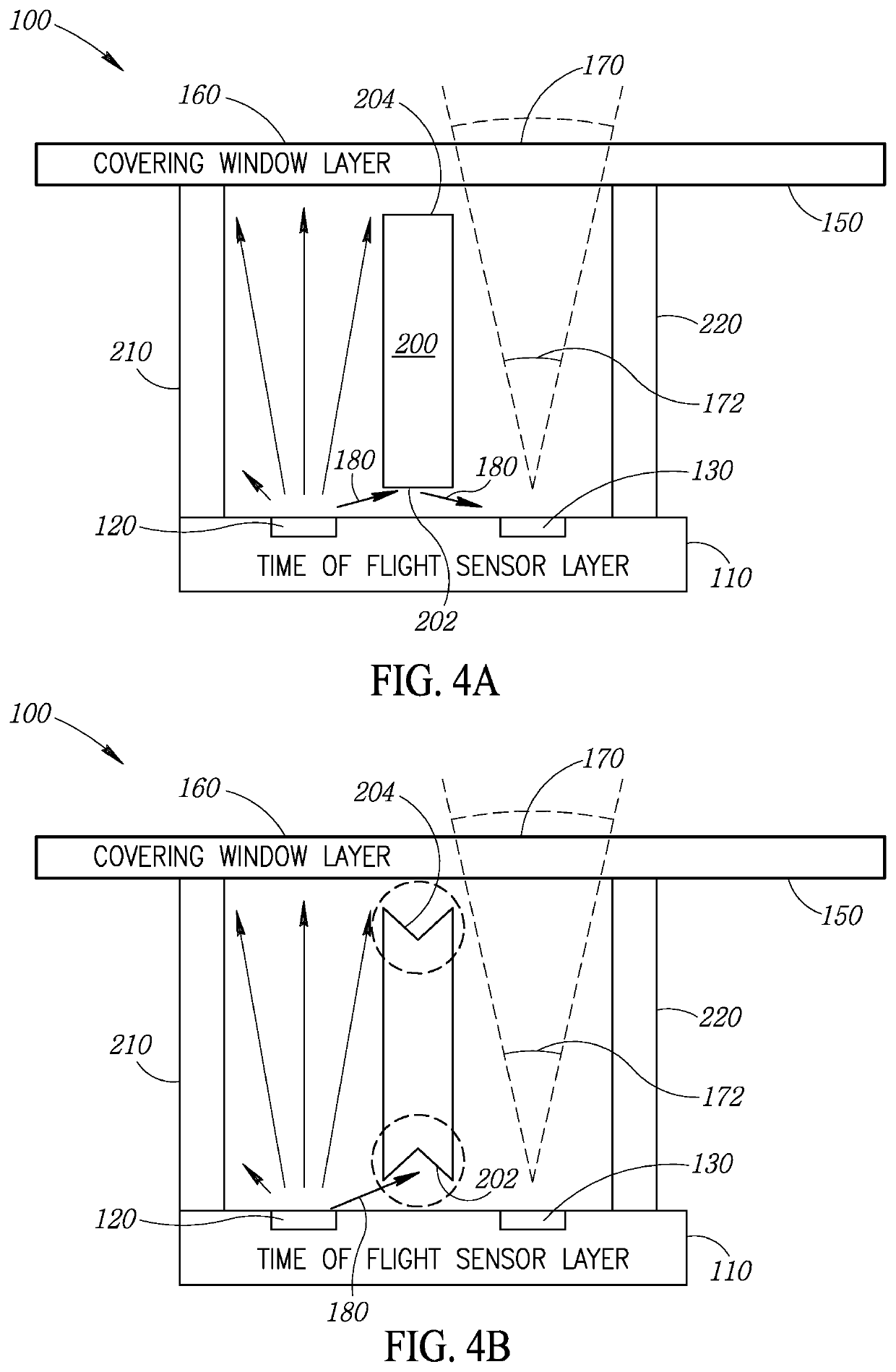
The present invention is about a time of flight sensor system that includes a time of flight sensor layer, a covering window layer, and one or more opaque walls. These opaque walls are designed to reduce reflection backscatter of emission signals and reception signals, insulate the signals, and shape the signals' angles. The technical effects of this invention include reducing crosstalk and dust particle issues, as well as improving the system's performance and stability. Additionally, the invention includes light baffles and enhanced, non-planar surfaces to further reduce crosstalk and improve the system's performance.

Problems solved by technology

Since these time of flight sensors typically measure distances in the meter range, the emitted signal is very powerful and the receiving system is very sensitive.
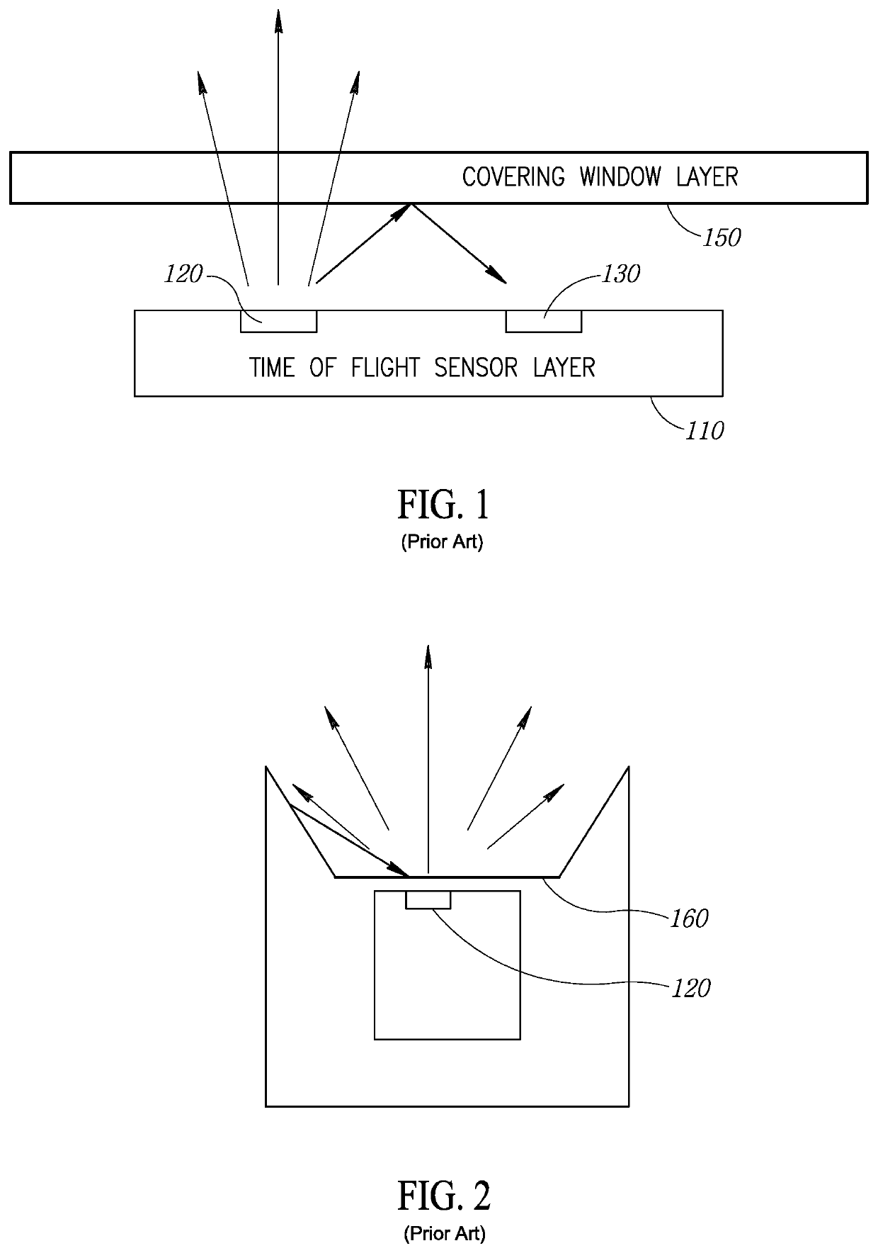
Unfortunately, this transparent wall of glass or plastic can induce cross talk between the emitting system and the receiving system, as shown in FIG. 1.
As a result, this “solution” creates a mechanical constraint that can be very limiting in the design of a machine-readable symbol reader.
Typically, a time of flight sensor has a working angle that may be wide, so that if the time of flight sensor is placed far from the exit surface of the machine-readable symbol reader, the surrounding mechanics can create spurious reflections.

Method used


Image

  • Time of flight sensor with light baffle system and method
  • Time of flight sensor with light baffle system and method
  • Time of flight sensor with light baffle system and method

Examples


Embodiment Construction

[0050]In the following description, certain specific details are set forth in order to provide a thorough understanding of various disclosed implementations. However, one skilled in the relevant art will recognize that implementations may be practiced without one or more of these specific details, or with other methods, components, materials, etc. In other instances, well-known structures associated with imagers and / or machine-readable symbol readers have not been shown or described in detail to avoid unnecessarily obscuring descriptions of the implementations.

[0051]Unless the context requires otherwise, throughout the specification and claims that follow, the word “comprising” is synonymous with “including,” and is inclusive or open-ended (i.e., does not exclude additional, unrecited elements or method acts).

[0052]Reference throughout this specification to “one implementation” or “an implementation” means that a particular feature, structure or characteristic described in connectio...


PUM


Abstract

A time of flight sensor system having a time of flight sensor layer is disclosed. The system includes a covering window layer spaced apart from the time of flight sensor layer, with an exit window and an entrance window, an emitting element in the time of flight sensor layer that transmits an emission signal, a receiving element in the time of flight sensor layer that receives a reception signal, one or more opaque walls, and light baffles incorporated into the one or more opaque walls. The one or more opaque walls extend at least a portion of the distance from the time of flight sensor layer to the covering window layer. The one or more opaque walls reduce the reflection backscatter of emission signals and reception signals. The light baffles in the one or more opaque walls reduce backscatter of emission signals and reception signals.

Description

TECHNICAL FIELD[0001]The present disclosure relates to a time of flight sensor, and more particularly to a time of flight sensor with a light baffle system.BACKGROUNDDescription of the Related Art[0002]Machine-readable symbol readers, such as scanners (e.g., flying spot type) and imager-based machine-readable symbol readers, have become ubiquitous in today's environment. Such machine-readable symbol readers have been used to detect and capture one-dimensional machine-readable symbols (e.g., barcode symbols) and two-dimensional machine-readable symbols (e.g., matrix symbols, Quick Response code symbols, PDF417 symbols) that have been attached to, inscribed or otherwise physically associated with various physical objects.[0003]Time of flight sensors are often employed in machine-readable symbol readers that employ distance to target (e.g., range) information to make the decoding more efficient. Typically, the machine-readable symbol reader adjusts the focus in autofocus systems based ...

Claims


Application Information

Patent Timeline
Patent Type & Authority Patents(United States)
IPC IPC(8): G01S7/481G01J1/02H03K17/945G01V8/10G01S17/894G01S7/4912G01J1/04G01J1/42
CPCG01S7/4813G01J1/0214G01S17/894G01V8/10H03K17/945G01J1/0422G01J2001/4247G01S7/4918
Inventor GNAN, MARCOQUATTRINI, PAOLO
Owner DATALOGIC IP TECH
Learn More