Leadframe alteration to direct compound flow into package

a technology of leadframe and package, which is applied in the field of leadframe, can solve the problems of less effective protective structure, unable to ensure the safety of the mold, and the molding compound entering the bottom gated mold tends to conglomerate, so as to increase the pressure differential, increase the flow of compound, and increase the effect of compound flow

Inactive Publication Date: 2006-05-30
MICRON TECH INC
View PDF19 Cites 5 Cited by
  • Summary
  • Abstract
  • Description
  • Claims
  • Application Information

AI Technical Summary

Benefits of technology

[0013]The aforementioned needs are satisfied by the leadframe of the present invention. In one aspect, the present invention discloses a leadframe wherein the leadframe comprises a plurality of lead fingers and a die paddle adapted to receive the die and a second offset positioned adjacent an edge of the leadframe. In this aspect, the second offset is positioned so as to increase the pressure differential between the first and the second surfaces of the leadframe so as to increase the flow of compound from the first surfaces to the second surface via the spaces between the plurality of lead fingers. In this way, the flow of compound can be increased without requiring limited space on the leadframe be occupied by flow openings and the like.
[0015]In one embodiment, the leadframe further comprises a tie bar wherein an outer end of the tie bar is generally triangular and comprises the offset. Preferably, in an encapsulation process, the leadframe is placed inside a mold cavity in a manner such that the offset is positioned adjacent a gate. Preferably, the offset is designed to receive a portion of the molding compound entering from the gate and guide the portion to flow toward the second surface of the leadframe. In particular, the offset produces a localized increase in the pressure of the compound flowing from the gate. This localized increase in pressure results in a greater pressure differential between the side of the leadframe adjacent the gate and the side opposite the gate thereby increasing the flow from the side adjacent the gate to the side opposite the gate.
[0016]Advantageously, the altered leadframe of the preferred embodiment provides an offset comprising a sloped surface strategically positioned to facilitate the flow of the molding compound as the compound enters the cavity from a gate. In particular, the altered leadframe splits the flow of the compound as the compound enters from a gate so as to ensure a more even distribution of the compound between the top and bottom of the leadframe.

Problems solved by technology

However, one disadvantage of the standard encapsulation process is that the mold cavity configuration and positioning of the leadframe therein preclude the molding compound from flowing evenly inside the cavity.
This can cause an uneven distribution of resin around the die and the leadframe resulting in a less effective protective structure.
Hence, molding compound entering from a bottom gated mold tends to conglomerate near the bottom of the cavity because its upward flow path is hindered by numerous horizontally extended leadframe fingers.
Disadvantageously, non-uniform compound flow rate in the mold and uneven resin distribution between the top and bottom surface of the leadframe are known to cause defects such as voids, pinholes, and knitlines in the cured plastic enclosure.
However, it can be appreciated that mold modifications with prepackaged inserts are costly to implement and therefore undesirable in light of the ever increasing demand for cost reduction in semiconductor fabrication.
Furthermore, the diverter is positioned away from the gate and therefore unable to direct the flow of the compound at the point where the resin first enters the cavity.
Moreover, the leadframe diverters as suggested by prior art are essentially unsupported flaps that can be easily damaged during the encapsulation process.
Furthermore, leadframes with the flow diverters as suggested by prior art are time consuming to manufacture as it requires additional processing steps to ensure that the diverters bend at a particular angle relative to the leadframe.
It will be appreciated that given the ever increasing need for greater density devices, the space on the die paddles and on the lead frame is becoming increasingly limited.
Hence, for many high density leadframe designs, forming openings simply for resin flow is impractical and inefficient.

Method used


Image

  • Leadframe alteration to direct compound flow into package
  • Leadframe alteration to direct compound flow into package
  • Leadframe alteration to direct compound flow into package

Examples


Embodiment Construction

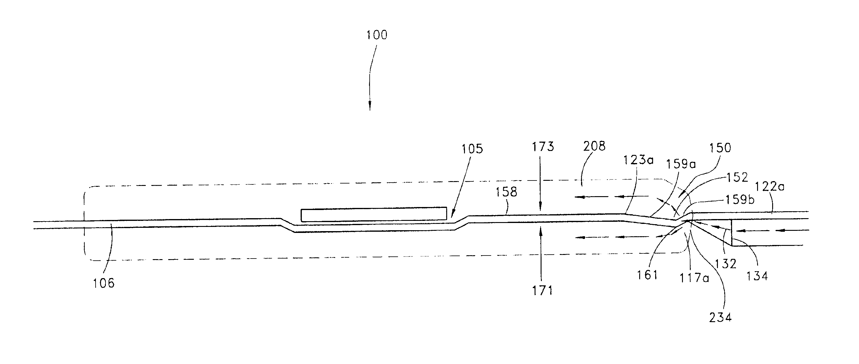
[0021]Reference will now be made to the drawings wherein like numerals refer to like parts throughout. As will be described hereinbelow, the leadframe of the preferred embodiment provides a leadframe that effectively directs the molding compound to flow evenly around the die and leadframe during encapsulation so as to reduce voids and pinholes in the encapsulated lead frame that typically result from uneven resin flow inside the mold cavity.

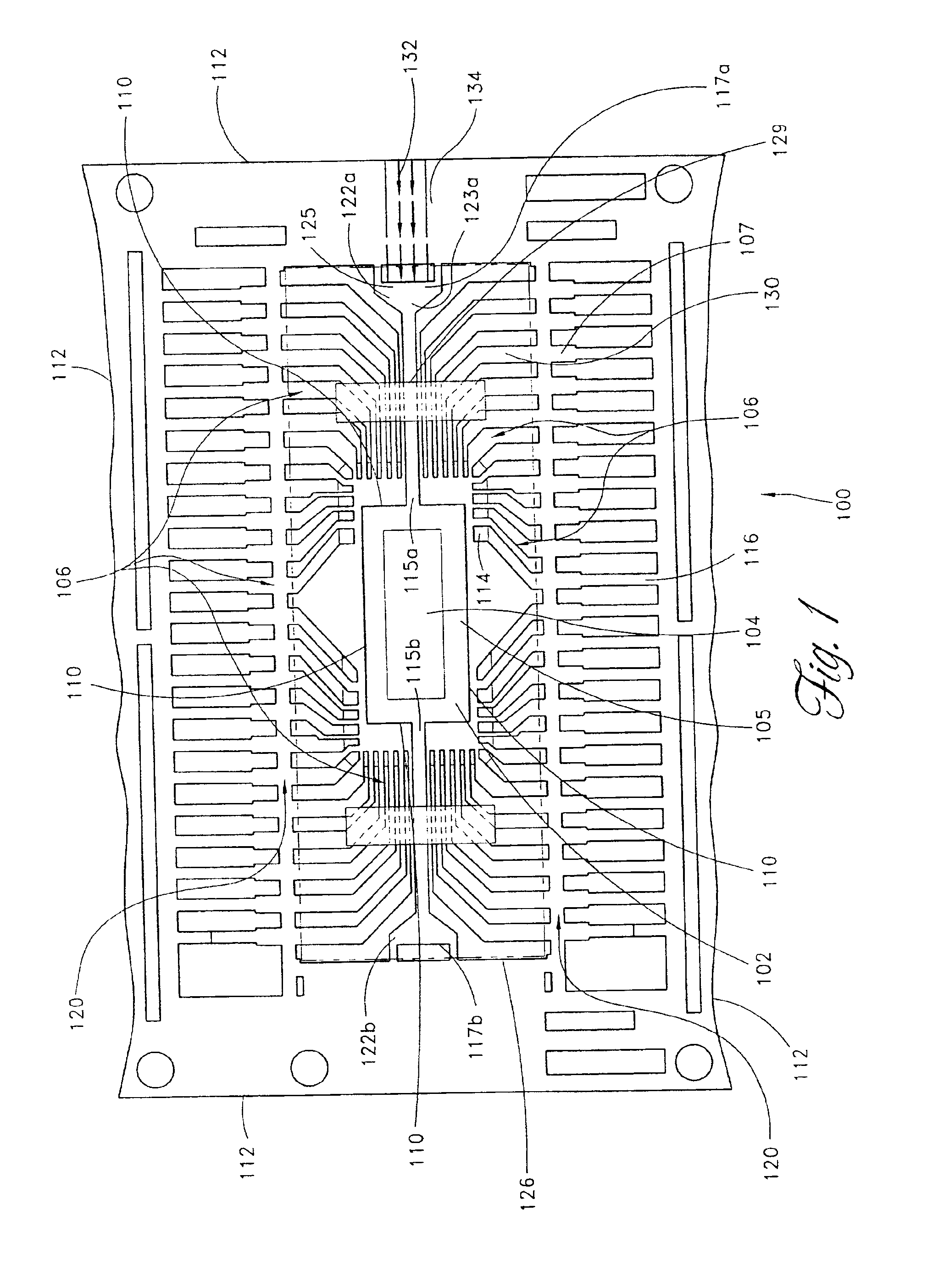
[0022]FIG. 1 illustrates a general top down view of a leadframe 100 of the preferred embodiment. As is shown in FIG. 1, the leadframe 100 is generally rectangular in shape and is typically made from a thin sheet of metal such as a copper or nickel alloy. As will be described in greater detail below, the leadframe 100 is designed to provide structural support for a die or chip and also facilitate electrical interconnection to the components formed on the die. In the typical packaging process, the die is encapsulated in a plastic enclosure. Further...


PUM


Abstract

A leadframe comprising a downset formed adjacent to an edge of the leadframe so as to direct the molding compound to flow evenly inside the mold cavity. The downset has an upward slope extending from the edge of the frame and levels off with the rest of the frame at a first transition point. The upward slope facilitates the upward flow of the molding compound entering from a bottom gate. Likewise, the leadframe also directs flow in a top gated mold by reversing the orientation of the leadframe or by forming a reverse downset on the leadframe.

Description

RELATED APPLICATIONS[0001]This application is a divisional application of U.S. application Ser. No. 09 / 898,345, filed Jul. 3, 2001 now U.S. Pat. No. 6,451,629 which is a divisional application of U.S. application Ser. No. 09 / 489,113, filed Jan. 21, 2000 now U.S. Pat. No. 6,278,175.BACKGROUND OF THE INVENTION[0002]1. Field of the Invention[0003]This invention relates to packaging of semiconductor integrated circuits and, more particularly, to a leadframe that directs the molding compound to flow evenly into the package during the encapsulation process.[0004]2. Description of the Related Art[0005]Semiconductor packaging generally involves incorporating completely fabricated chips, generally referred to as a die, into protective packages so that the dies are protected from environmental contaminants and handling damage. A common method for packaging integrated circuits comprises bonding each die to a leadframe and subsequently encapsulating the die and a portion of the leadframe in a m...

Claims


Application Information

Patent Timeline
Patent Type & Authority Patents(United States)
IPC IPC(8): H01L23/495H01L21/44H01L21/48H01L21/50H01L21/56
CPCH01L21/565H01L23/49551H01L2924/0002H01L2924/00
Inventor JAMES, STEPHEN L.
Owner MICRON TECH INC
Why Eureka
Try Eureka