Track-and-hold peak detector circuit

a detector circuit and track-and-hold technology, applied in the field of track-and-hold peak detector circuits, can solve the problems of degrading accuracy and repeatability of the peak detector circuit, large capacitors are not readily integrated onto a common substrate with other circuitry, and the voltage on the capacitor tends to drift with time, so as to achieve small value, size and cost, and low operating frequency

Active Publication Date: 2006-05-30
ALLEGRO MICROSYSTEMS INC
View PDF5 Cites 25 Cited by
  • Summary
  • Abstract
  • Description
  • Claims
  • Application Information

AI Technical Summary

Benefits of technology

[0022]With the above arrangements, circuits are provided that can avoid the effect of a voltage drift on a capacitor used in a peak detector circuit. By avoiding the effect of the voltage drift, the capacitor can be made smaller in value, size, and cost, while maintaining a very low operating frequency.

Problems solved by technology

In conventional track-and-hold peak detector circuits, or more simply, peak detector circuits, it is known that the voltage on the capacitor tends to drift with time due to leakage currents in the capacitor itself and also due to leakage currents in circuitry surrounding the capacitor.
As is known, high temperatures tend to result in relatively high leakage currents, and therefore, a relatively high voltage drift in a voltage held on a capacitor used in the peak detector circuit.
As is known, large capacitors are not readily integrated onto a common substrate with other circuitry.
Use of the external capacitor increases sensitivity of the peak detector circuit to electrical noise from external noise sources, which can degrade accuracy and repeatability of the peak detector circuit.
The external capacitor also tends to be undesirably large and can also be costly.
However, the dual-polarity peak detector is also subject to self-switching.
From the above discussion, it should be apparent that prior art peak detector arrangements used to reduce self-switching are not suitable for low-frequency high-temperature operation.
Furthermore, having an external holding capacitor, prior art peak detectors tend to be relatively large.

Method used


Image

  • Track-and-hold peak detector circuit
  • Track-and-hold peak detector circuit
  • Track-and-hold peak detector circuit

Examples


Embodiment Construction

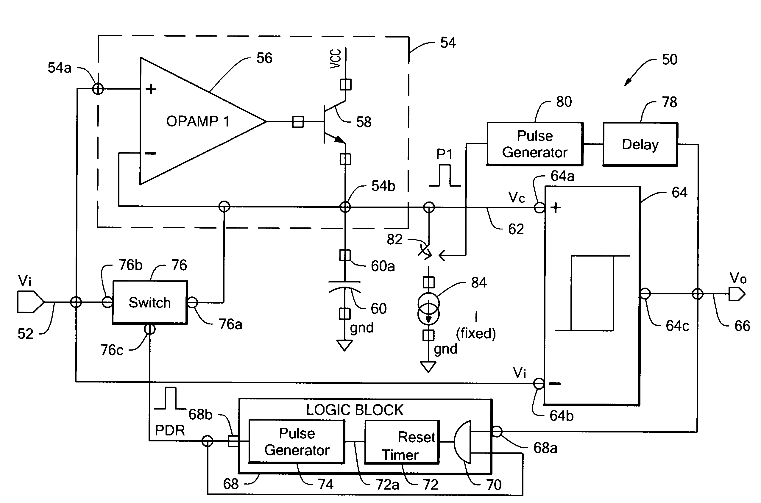
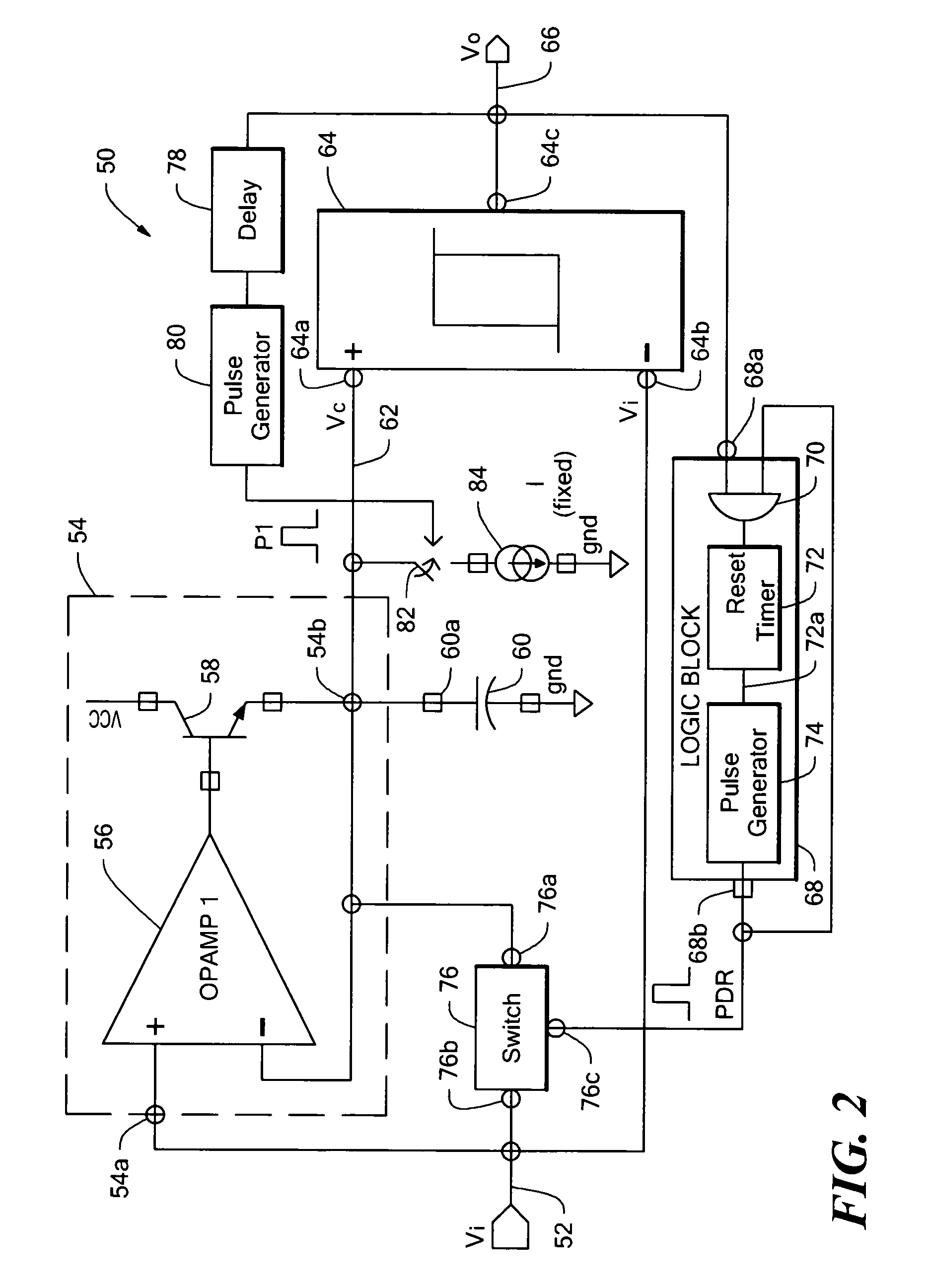
[0033]Before describing the peak detector circuit, some introductory concepts and terminology are explained. As used herein, the term “proximity sensor” refers to a circuit that can detect peaks and / or thresholds associated with an output signal generated by one or more magnetic field sensors in response to presence or absence of a ferrous object, for example, a tooth of a ferrous gear, or in response to presence or absence of a magnet.

[0034]Referring to FIG. 2, a circuit 50 includes a capacitor 60 having a threshold node 60a. The circuit 50 also includes a charging circuit 54 having a charging circuit input node 54a to receive an input signal 52 and a charging circuit output node 54b coupled to the threshold node 60a. The circuit 50 is responsive to positive peaks of the input signal 52. A similar circuit, which is responsive to negative peaks of the input signal, is shown below in FIG. 9.

[0035]The circuit 50 also includes a comparator 64 having a first comparator input node 64a co...


PUM


Abstract

A track-and-hold peak detector circuit, which can operate at low input signal frequencies, includes a capacitor to hold a peak voltage of the input signal and logic circuitry that reduces an effect of leakage current into or out of the capacitor, and therefore, provides protection against self-switching of an output signal of the peak detector circuit.

Description

CROSS REFERENCE TO RELATED APPLICATIONS[0001]Not Applicable.STATEMENT REGARDING FEDERALLY SPONSORED RESEARCH[0002]Not Applicable.FIELD OF THE INVENTION[0003]This invention relates to track-and-hold peak detector circuits and, more particularly, to track-and-hold peak detector circuits that use a capacitor to hold a voltage.BACKGROUND OF THE INVENTION[0004]Track-and-hold peak detector circuits having a capacitor to hold a voltage corresponding to an input signal are known. In conventional track-and-hold peak detector circuits, or more simply, peak detector circuits, it is known that the voltage on the capacitor tends to drift with time due to leakage currents in the capacitor itself and also due to leakage currents in circuitry surrounding the capacitor.[0005]Conventional proximity sensors are also known, which can detect, for example, peaks and / or thresholds associated with an output signal generated by one or more magnetic field sensors in response to presence or absence of a ferro...

Claims


Application Information

Patent Timeline
Patent Type & Authority Patents(United States)
IPC IPC(8): G11C27/02
CPCG11C27/026G11C27/024
Inventor ROMERO, HERNAN D.TOWNE, JAY M.SCHELLER, KARL
Owner ALLEGRO MICROSYSTEMS INC
Why Eureka
Try Eureka