Combination aircraft antenna assemblies

a technology of aircraft antennas and components, applied in the field of aircraft antennas, can solve the problems of interference between the harmonics generated by one antenna and the frequency bands of other antennas, and interfere with the aerodynamic performance of an aircra

Inactive Publication Date: 2006-05-30
COMANT INDS
View PDF2 Cites 38 Cited by
  • Summary
  • Abstract
  • Description
  • Claims
  • Application Information

AI Technical Summary

Benefits of technology

[0004]According to an embodiment of the invention an aircraft antenna includes an integrated low profile shielded harmonic suppression filter that permits close placement of antennas.

Problems solved by technology

However, the limited space on the outer surface of an aircraft may require placement of the multiple antennas in close enough proximity to each other to create radio interference between them.
In particular, harmonics generated by one antenna may interfere with coincident frequencies in the frequency bands of other antennas.
Moreover the various antennas project from the outer surface of the aircraft and introduce drag that interferes with the aerodynamic performance of an aircraft.

Method used


Image

  • Combination aircraft antenna assemblies
  • Combination aircraft antenna assemblies
  • Combination aircraft antenna assemblies

Examples


Embodiment Construction

[0004]According to an embodiment of the invention an aircraft antenna includes an integrated low profile shielded harmonic suppression filter that permits close placement of antennas.

[0005]According to another embodiment of the invention, two antenna radiators are combined in a single aerodynamic housing to form a single combination antenna and one radiator includes an integrated harmonic suppression filter.

[0006]These and other features of the invention are pointed out in the claims. Other aspects of the invention will become evident from the following detailed description when read in light of the accompanying drawings.

BRIEF DESCRIPTION OF THE DRAWINGS

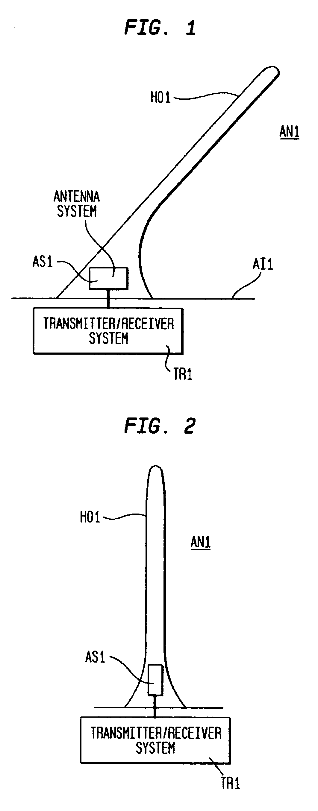
[0007]FIG. 1 is a schematic illustration including a side view of an antenna mounted on an airframe and embodying features of the invention.

[0008]FIG. 2 is a schematic diagram including a front view of the antenna in FIG. 1 mounted on an airframe and embodying features of the invention.

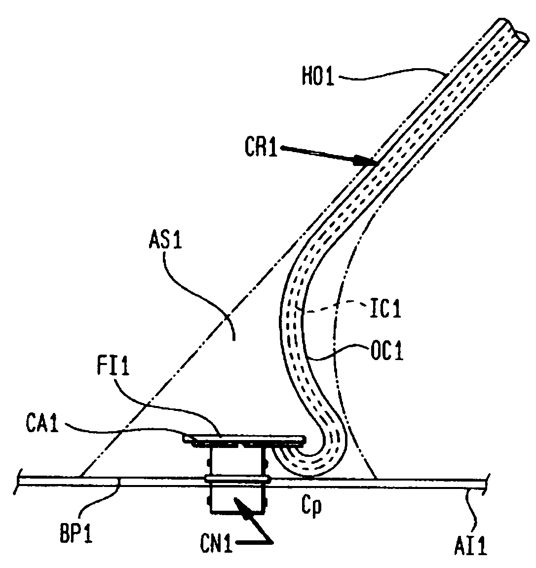
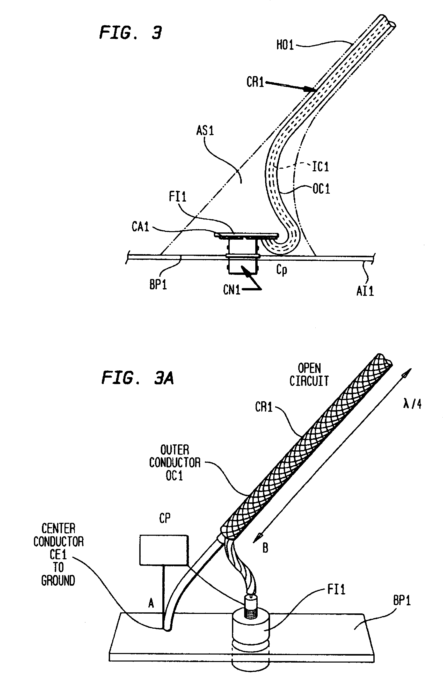
[0009]FIG. 3 shows details of the antenna in FIG...


PUM


Abstract

An aircraft antenna includes an aerodynamic housing structured for attachment to an outer surface of an aircraft, and the housing contains an electromagnetic radiator and tuned over a first band of frequencies potentially to produce secondary radiations in at least a second band of frequencies, and a suppression filter effective at the frequencies of the secondary radiations.

Description

RELATED APPLICATIONS[0001]This invention relates to U.S. application Ser. No. 60 / 439,252 filed Jan. 10, 2003 and entitled “Combination Antennas”, and to U.S. application Ser. No. 60 / 439,381 filed Jan. 10, 2003 and entitled “Combination Antennas”. Applicant claims the benefit of these applications under 35 USC 120.FIELD OF THE INVENTION[0002]This invention relates to aircraft antennas, and particularly to aircraft antennas that limit drag on an aircraft while avoiding interference with each other.BACKGROUND OF THE INVENTION[0003]Aircraft carry a number antennas for navigational, communication, and other purposes. However, the limited space on the outer surface of an aircraft may require placement of the multiple antennas in close enough proximity to each other to create radio interference between them. In particular, harmonics generated by one antenna may interfere with coincident frequencies in the frequency bands of other antennas. Moreover the various antennas project from the out...

Claims


Application Information

Patent Timeline
Patent Type & Authority Patents(United States)
IPC IPC(8): H01Q21/00
CPCH01Q1/22H01Q23/00H01Q21/30H01Q1/28
Inventor HOLLOWAY, DAVID J.JECKELL, DONALD E.GOMEZ, RENE F.
Owner COMANT INDS
Why Eureka
Try Eureka