
Patterned-media magnetic recording disk with optical contrast enhancement and disk drive using optical contrast for write synchronization

a magnetic recording disk and optical contrast technology, applied in combination recording, data recording, instruments, etc., can solve problems such as difficulty in generating reliable radiation detector output signals

Active Publication Date: 2010-09-14
WESTERN DIGITAL TECH INC
View PDF21 Cites 18 Cited by
  • Summary
  • Abstract
  • Description
  • Claims
  • Application Information

AI Technical Summary

Benefits of technology

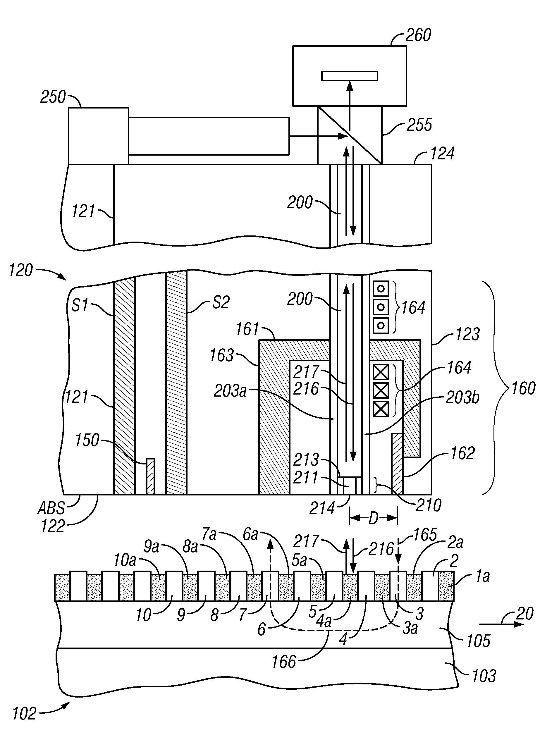
The invention is about a new type of magnetic recording disk drive that uses an optical system to help synchronize data writing. The disk has special spaces between the main data islands that contain contrast material, which can absorb or emit light. This allows the system to detect the position of the islands as the disk rotates. The system uses a primary optical waveguide and a secondary radiation source to excite the contrast material in the spaces, which results in significantly different power levels than the interaction with the islands. This allows for more precise synchronization of data writing. Overall, the invention improves the accuracy and efficiency of magnetic recording disk drives.

Problems solved by technology

However, the difference in reflected radiation power from the transducer between an island and a recess can be relatively small, making it difficult to generate a reliable radiation detector output signal.

Method used


Image

  • Patterned-media magnetic recording disk with optical contrast enhancement and disk drive using optical contrast for write synchronization
  • Patterned-media magnetic recording disk with optical contrast enhancement and disk drive using optical contrast for write synchronization
  • Patterned-media magnetic recording disk with optical contrast enhancement and disk drive using optical contrast for write synchronization

Examples


Embodiment Construction

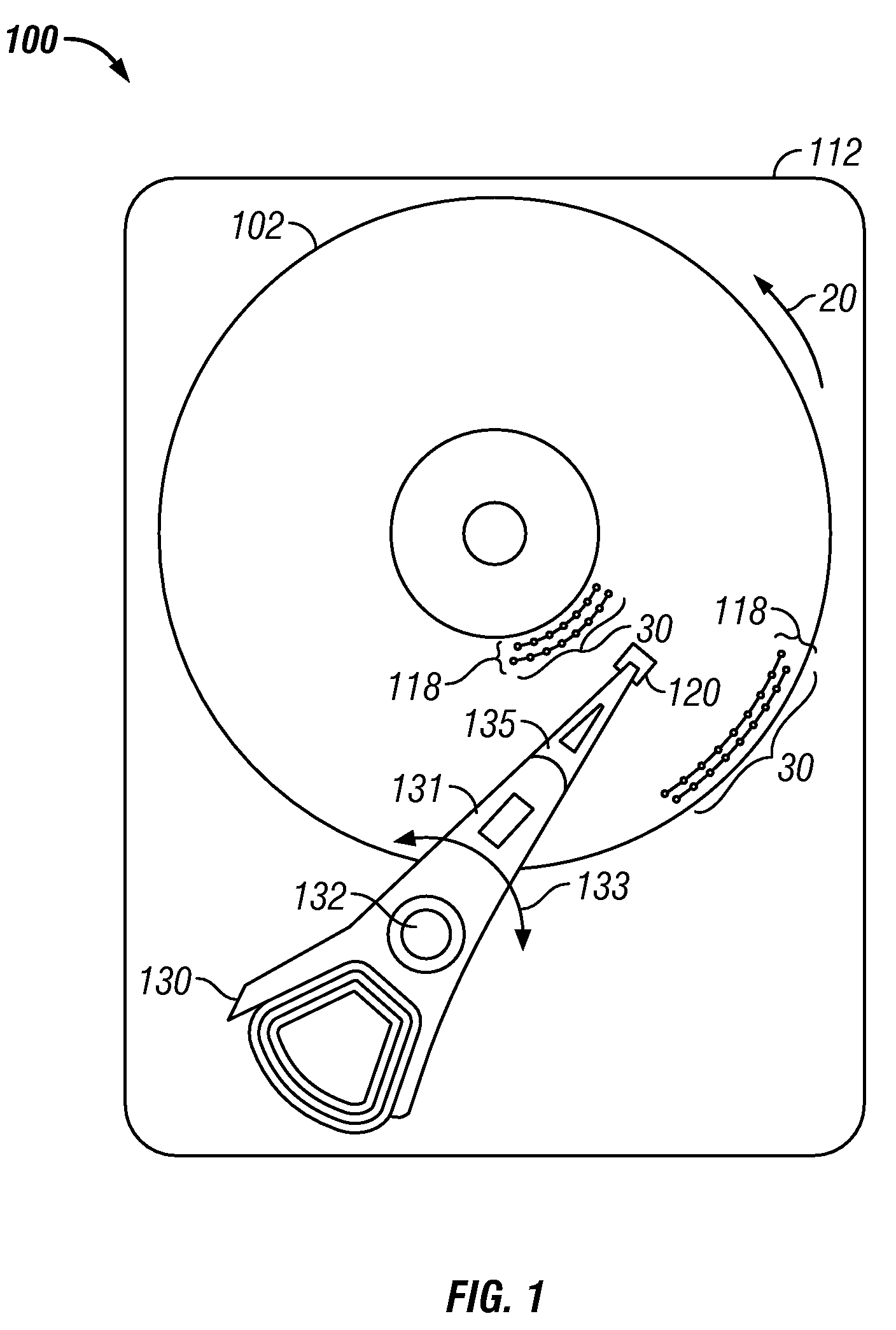
[0028]FIG. 1 is a top view of a patterned-media magnetic recording disk drive 100 with a patterned-media magnetic recording disk 102. The drive 100 has a housing or base 112 that supports an actuator 130 and a drive motor for rotating the magnetic recording disk 102. The actuator 130 may be a voice coil motor (VCM) rotary actuator that has a rigid arm 131 and rotates about pivot 132 as shown by arrow 133. A head-suspension assembly includes a suspension 135 that has one end attached to the end of actuator arm 131 and a head carrier, such as an air-bearing slider 120, attached to the other end of suspension 135. The suspension 135 permits the slider 120 to be maintained very close to the surface of disk 102 and enables it to “pitch” and “roll” on the air-bearing generated by the disk 102 as it rotates in the direction of arrow 20. A magnetoresistive read head (not shown) and an inductive write head (not shown) are typically formed as an integrated read / write head patterned as a serie...


PUM

PropertyMeasurementUnit
sizeaaaaaaaaaa
sizeaaaaaaaaaa
wavelengthaaaaaaaaaa

Abstract

A patterned-media magnetic recording disk drive uses an optical system for clocking the write data and a patterned-media disk that has discrete magnetizable data islands with nonmagnetic spaces between the islands, wherein the nonmagnetic spaces contain optical contrast material. The optical contrast material may be optically absorptive material, fluorescent material, or a metal layer that generates surface plasmons when excited by radiation of a specific wavelength. Radiation from a primary radiation source is directed to a near-field transducer maintained near the disk surface and a radiation detector detects radiation reflected back from the transducer. If the disk has fluorescent material or a metal layer in the nonmagnetic spaces, then a secondary radiation source irradiates the fluorescent material or metal layer with radiation of a specific wavelength to cause the fluorescent material to emit radiation or the metal layer to generate surface plasmons. As the disk rotates, reflected optical power from the transducer varies depending on whether an island or space is under the transducer. The output signal from the radiation detector output controls the write clock.

Description

RELATED APPLICATION[0001]This application is related to pending application Ser. No. 12 / 209,089 filed Sep. 11, 2008, titled “MAGNETIC RECORDING DISK DRIVE WITH PATTERNED MEDIA AND OPTICAL SYSTEM FOR CLOCKING WRITE DATA”, and assigned to the same assignee as this application.BACKGROUND OF THE INVENTION[0002]1. Field of the Invention[0003]This invention relates generally to magnetic recording disk drives for use with patterned media, wherein each data bit is stored in a magnetically isolated island or island on the disk, and more particularly to such a disk drive with an improved clock for writing the data.[0004]2. Description of the Related Art[0005]Magnetic recording hard disk drives with patterned magnetic recording media have been proposed to increase the data density. In patterned media, the magnetic material on the disk is patterned into small isolated data islands or islands arranged in concentric data tracks. Each island contains a single magnetic “bit” and is separated from n...

Claims


Application Information

Patent Timeline
Patent Type & Authority Patents(United States)
IPC IPC(8): G11B5/02
CPCB82Y10/00G11B5/314G11B5/59677G11B5/6088G11B5/743
Inventor SCHABES, MANFRED ERNSTSTIPE, BARRY CUSHINGZELTZER, GABRIEL
Owner WESTERN DIGITAL TECH INC
Learn More