Device for shielding a transponder, method for producing a corresponding shielding and transponder provided with said shielding

a transponder and shielding technology, applied in the direction of antennas, burglar alarms by hand-held articles removal, antenna supports/mountings, etc., can solve the problems of inability to mount a transponder, inability to supply energy to and data transmission from the chip of the transponder, and damp magnetic field on the surface, etc., to achieve moderate price, suppress eddy current, and suppress eddy current

Inactive Publication Date: 2006-05-30
FLEXCHIP
View PDF13 Cites 11 Cited by
  • Summary
  • Abstract
  • Description
  • Claims
  • Application Information

AI Technical Summary

Benefits of technology

[0019]Higher values can be obtained by compact magnetic conductors, e.g., layers or compact films of highly permeable metals. For suppressing the above-mentioned eddy currents, these magnetic conductors must be structured such that they suppress a flow of current in the direction of the induced electric field. Such eddy currents extract energy from the field, and this will lead, on the one hand, in a reduction of the amount of useful energy that can be transmitted and, on the other hand, in a damping of the antenna circuit with disadvantageous effects on data transmission. A similar phenomenon is known from the field of electrical engineering, e.g., when mutually insulated blade fins are provided on transformers.
[0020]Proceeding from the known prior art, it is the object of the present invention to provide a possibility of operating an RFID system in metal surroundings as trouble-free as possible.
[0021]This object is achieved by the subject matters of the independent claims. Preferred embodiments of the present invention are subject matters of the subclaims.
[0022]The object of the present invention is especially achieved by a unit for shielding a transponder, which comprises at least a chip and an antenna structure with application-specific spatial dimensions and which is attached to an electrically conductive surface.
[0023]According to one aspect of the present invention, this unit comprises a film having formed thereon or therein a highly permeable material at least in an area having the spatial dimensions of the antenna structure of the transponder. The highly permeable material is subdivided into elongate shielding elements and free spaces arranged between the respective shielding elements, in such a way that, when the substrate has been secured to the transponder, the shielding elements will be oriented parallel to a magnetic field induced in the antenna structure of the transponder, so as to suppress eddy currents which are generated by the electrically conductive surface in the antenna structure, when the transponder is being introduced in a magnetic field of a respective reading device.
[0024]According to another aspect of the present invention, said unit comprises a substrate having formed thereon a plurality of fixed ferromagnetic particles in an area having at least the spatial dimensions of the antenna structure of the transponder. The respective ferromagnetic particles are oriented such that, when the substrate has been attached to the transponder, they will be oriented parallel to a magnetic field induced in the antenna structure of the transponder, so as to suppress eddy currents which are generated by the electrically conductive surface in the antenna structure, when the transponder is being introduced in a magnetic field of a respective reading device.

Problems solved by technology

The mounting of a transponder, including, e.g., a high-frequency conductor loop, directly on a metallic surface is, however, not easily possible.
The alternating magnetic flux through the metal surface induces eddy currents in the conductor loop which counteract the cause, i.e., the field of the conductor loop, and which therefore damp the magnetic field on the surface to such an extent that a supply of energy to and data transmission from the chip of the transponder are no longer possible.
Shielding against high-frequency fields is a general problem that arises in the field of technology; in the case of RFID technology, this problem has, however, a special aspect: in RFID systems, the position of the electric or magnetic field which is to be shielded against or to be conducted more precisely is known because it is defined by the geometry of the antenna structure arranged in close vicinity to the metallic support.
Such eddy currents extract energy from the field, and this will lead, on the one hand, in a reduction of the amount of useful energy that can be transmitted and, on the other hand, in a damping of the antenna circuit with disadvantageous effects on data transmission.

Method used


Image

  • Device for shielding a transponder, method for producing a corresponding shielding and transponder provided with said shielding
  • Device for shielding a transponder, method for producing a corresponding shielding and transponder provided with said shielding
  • Device for shielding a transponder, method for producing a corresponding shielding and transponder provided with said shielding

Examples


Embodiment Construction

[0043]The illustrative embodiments of the present invention will be described with reference to the figure drawings, wherein like elements and structures are indicated with like reference numbers.

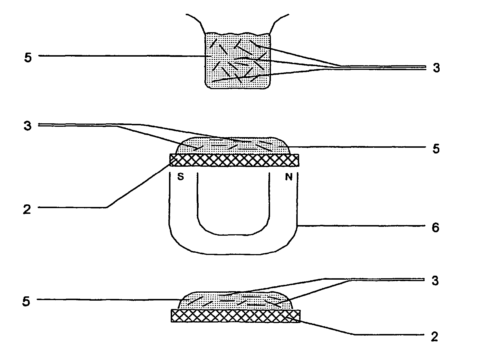
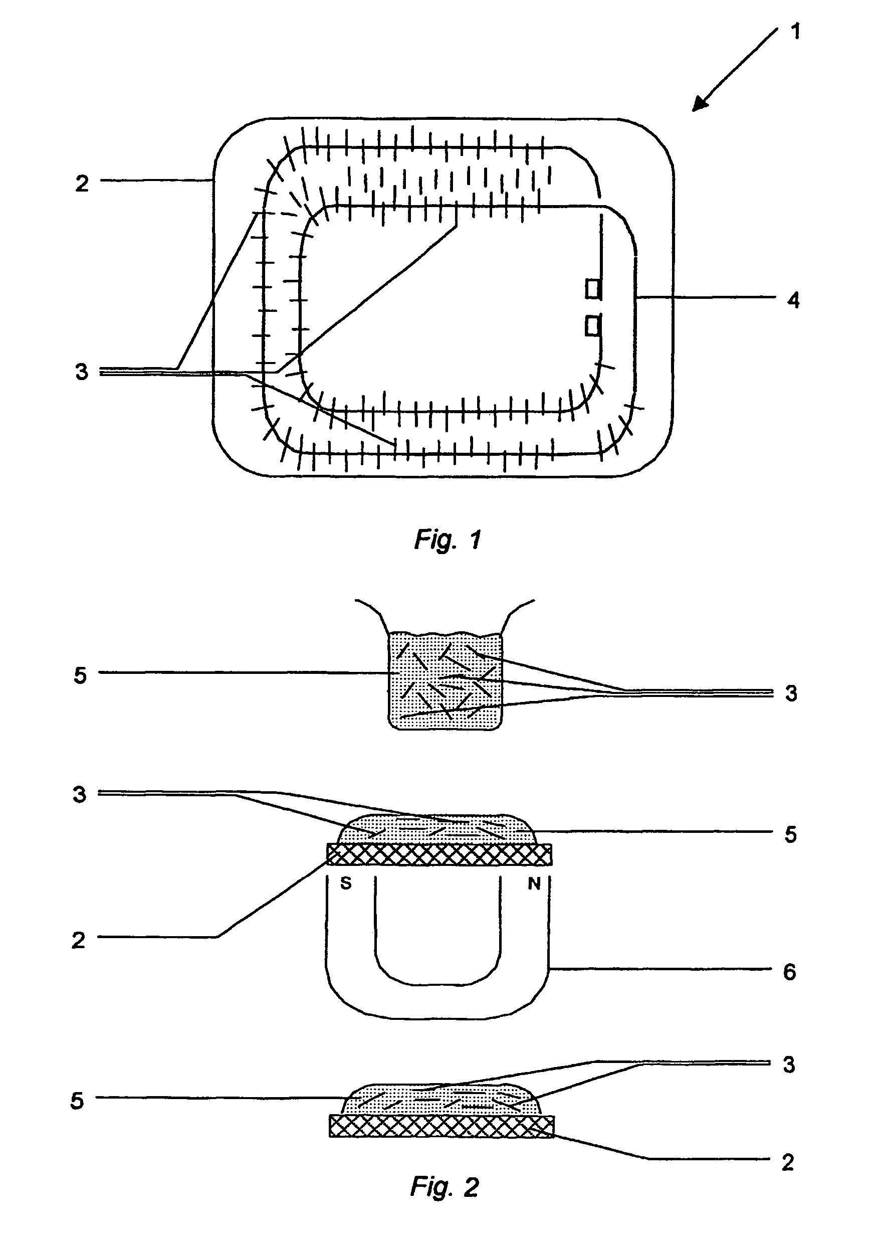
[0044]FIG. 1 shows a unit 1 for shielding a transponder, which comprises at least a chip and an antenna structure 4 with application-specific spatial dimensions and which is secured to an electrically conductive surface, according to a first aspect of the present invention. The antenna structure 4 shown in FIG. 1 represents a conductor loop and an antenna coil, respectively.

[0045]The unit 1 comprises a substrate 2 having formed thereon a plurality of fixed ferromagnetic particles 3 in an area having at least the spatial dimensions of the antenna structure 4 of the transponder.

[0046]The antenna structure 4 of the transponder is shown in FIG. 1 only for clearly indicating this area on the substrate 2, said antenna structure 4 being, however, not visible when the shielding itself is being prod...


PUM


Abstract

A unit for shielding a transponder includes at least a chip and an antenna structure with application-specific spatial dimensions and which is secured to an electrically conductive surface. The unit includes a film having formed thereon or therein a highly permeable material at least in an area having the spatial dimensions of the antenna structure of the transponder. The highly permeable material is subdivided into elongate shielding elements and free spaces arranged between the respective shielding elements such that when the substrate has been attached to the transponder, the shielding elements will be oriented parallel to a magnetic field induced in the antenna structure of the transponder, so as to suppress eddy currents which are generated by the electrically conductive surface in the antenna structure, when the transponder is being introduced in a magnetic field of a respective reading device.

Description

CROSS-REFERENCE TO RELATED APPLICATIONS[0001]This application is a 371 of PCT / EP02 / 11217, filed on Oct. 7, 2002.BACKGROUND OF THE INVENTION[0002]1. Field of the Invention[0003]The present invention relates to a shielding for a transponder comprising at least a chip and an antenna structure.[0004]2. Description of the Related Art[0005]In many spheres of public life, RFID systems for identifying arbitrary objects have increasingly been used within the last few years. The term RFID stands for Radio-Frequency-Identification and designates an identification by means of radio waves. An RFID system always comprises two components: an evaluation device that can be implemented as a read and / or write unit, and a transponder carrying the data used for identification.[0006]Transponders which are nowadays produced comprise a small-area chip and an antenna structure. The most common use of transponders are contactless chip cards, which are nowadays predominantly used as means of payment in the fo...

Claims


Application Information

Patent Timeline
Patent Type & Authority Patents(United States)
IPC IPC(8): H01Q1/52G06K19/077
CPCG06K19/07771G06K19/07749
Inventor PLETTNER, ANDREASSTEIN, ARNO
Owner FLEXCHIP
Why Eureka
Try Eureka