
Disk drive actuator-pivot assembly with corrugated rings

a technology of actuators and ring assemblies, which is applied in the direction of couplings, bearing units, rigid supports, etc., can solve the problems of mechanical deformation, actuator and servo performance degradation, and the mechanical performance of the actuator system is placed a great deal of burden

Inactive Publication Date: 2006-05-30
HITACHI GLOBAL STORAGE TECH NETHERLANDS BV
View PDF15 Cites 17 Cited by
  • Summary
  • Abstract
  • Description
  • Claims
  • Application Information

AI Technical Summary

Benefits of technology

[0008]In a preferred embodiment, the invention provides an effective mechanism which significantly equalizes the forces placed on a pivot cartridge as a result of being affixed in an actuator.
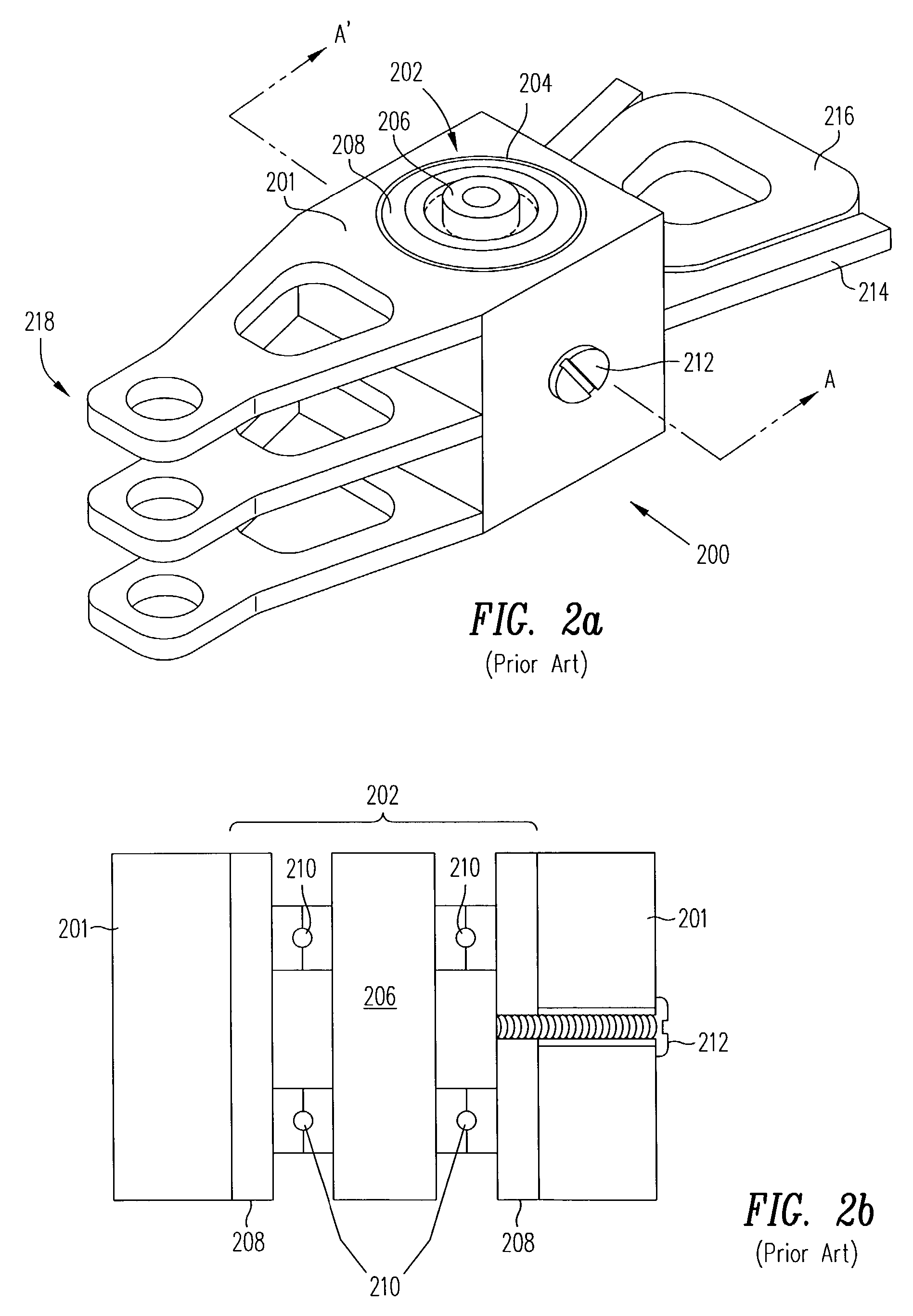
[0009]In one embodiment, corrugated end rings are used to affix the pivot cartridge in the bore of the actuator arm. Forces are distributed over several indentations of the corrugated end ring. Thus, the forces are much more uniformly distributed on the pivot cartridge. A corrugated end ring may be formed from stainless steel or other suitable material, and may be positioned by press fitting or swaging into the bore of the actuator arm. A groove may be formed in the bore of the actuator arm or in the pivot cartridge to provide a consistent mounting location for the corrugated end ring. A flange may be formed on the corrugated end ring to assist in positioning. Corrugated end rings are effective in reducing vibrations in the actuator.

Problems solved by technology

As the width of recorded tracks become more and more narrow, greater burdens are placed on the mechanical performance of the actuator system to accurately position the recording head over the track of interest.
Excess mechanical vibration, relatively large assembly tolerances, and mechanical distortions or deformations all contribute to a degradation of actuator and servo performance.
One source of mechanical deformation is the deleterious mechanical biasing which occurs when a pull screw is used to affix a pivot cartridge in the bore of an actuator arm.
The use of a pull screw in an actuator assembly leads to very asymmetrical and uneven forces placed on the pivot cartridge.
These uneven forces can make the assembly susceptible to vibrations and can degrade the performance of the actuator.

Method used


Image

  • Disk drive actuator-pivot assembly with corrugated rings
  • Disk drive actuator-pivot assembly with corrugated rings
  • Disk drive actuator-pivot assembly with corrugated rings

Examples


Embodiment Construction

[0035]As shown in the drawings for purposes of illustration, the invention is embodied in a novel actuator assembly having corrugated end rings positioned between an actuator bore and a cylindrical pivot cartridge. Corrugated end rings allow the forces placed on the pivot cartridge to be much more uniformly distributed thus reducing mechanical distortion, deformation, and vibration.

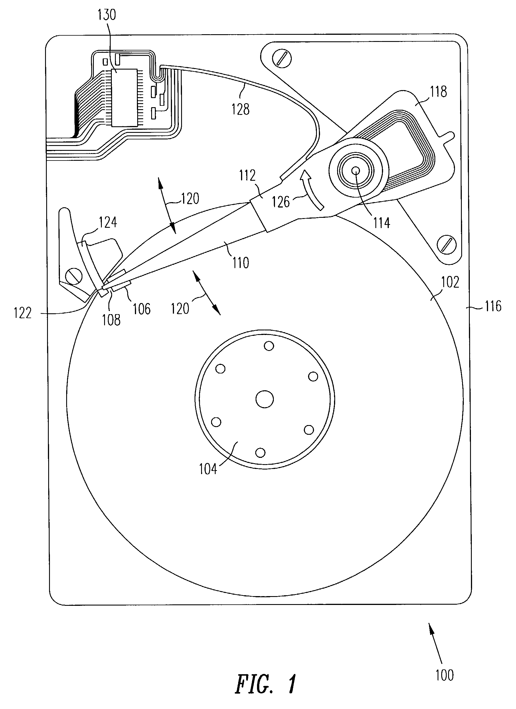
[0036]Referring to FIG. 1, a magnetic disk drive 100 has at least one rotatable magnetic disk 102 supported by a spindle 104 and rotated by a motor (not shown). There is at least one slider 106 with an attached recording head 108 positioned over the disk 102 surface while reading and writing. The slider 106 is attached to a suspension 110 and the suspension 110 is attached to an actuator 112 according to the present invention. The actuator 112 is pivotally attached 114 to the housing 116 of the disk drive 100 and is pivoted by a voice coil motor 118. As the disk is rotating, the actuator 112 positions the...


PUM


Abstract

An actuator assembly for a disk drive is provided wherein the pivot cartridge is supported within the bore of the actuator with corrugated end rings. The corrugated end rings provide a uniform distribution of forces on the pivot cartridge and effectively reduce vibrations between the pivot cartridge and the body of the actuator.

Description

BACKGROUND OF THE INVENTION[0001]1. Field of the Invention[0002]The invention relates in general to a servo actuator-pivot assembly in a magnetic recording disk drive; and, more particularly to an actuator-pivot assembly which has corrugated end rings.[0003]2. Description of the Background Art[0004]Disk drives using magnetic recording of digital information store most of the information in contemporary computer systems. A disk drive has at least one rotating disk with discrete concentric tracks of data. Each disk drive also has at least one recording head typically having a separate write element and read element for writing and reading the data on the tracks. The recording head is constructed on a slider and the slider is attached to a suspension. The combination of the recording head, slider, and suspension is called a head gimbal assembly. In addition, there is an actuator, part of a servo system, which positions the recording head over the specific track of interest. The actuato...

Claims


Application Information

Patent Timeline
IPC IPC(8): G11B5/55G11B21/08G11B5/48G11B21/02
CPCG11B5/4813F16C35/077F16C19/54F16D1/0835
Inventor DOMINGUEZ, JR., MIGUELMISRA, AMBRISHRADWAN, HATEM
Owner HITACHI GLOBAL STORAGE TECH NETHERLANDS BV
Learn More