Surrounding structure of a loudspeaker

Active Publication Date: 2006-05-30
PANASONIC CORP
View PDF5 Cites 36 Cited by
  • Summary
  • Abstract
  • Description
  • Claims
  • Application Information

AI Technical Summary

Benefits of technology

[0011]The present invention relates to a surround, which is used in a loudspeaker having a vibrating diaphragm and a frame, having a structure wherein the outer periphery is secured to the frame while the inner periphery is

Problems solved by technology

Therefore, reproduction of the low frequency range of so

Method used


Image

  • Surrounding structure of a loudspeaker
  • Surrounding structure of a loudspeaker
  • Surrounding structure of a loudspeaker

Examples


first embodiment

[0034](First Embodiment)

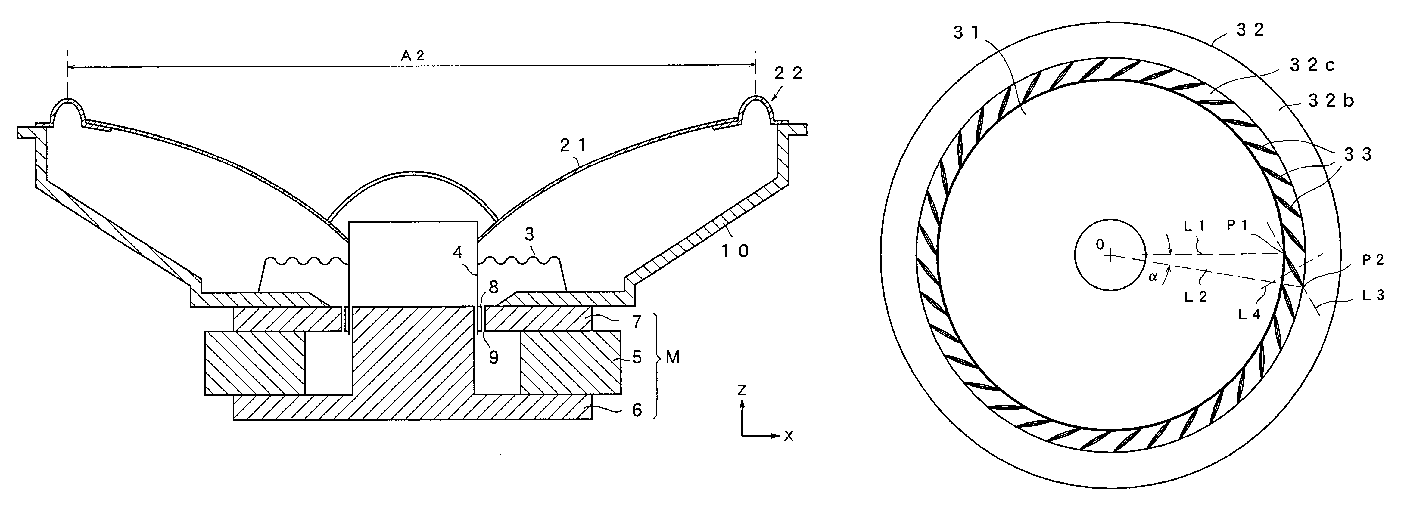
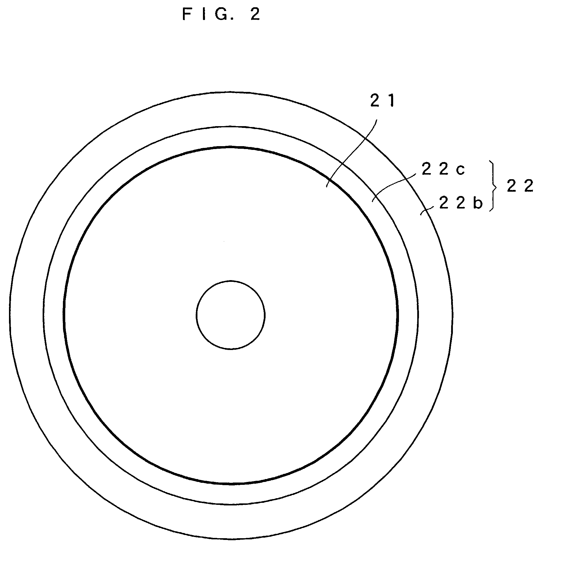
[0035]A surrounding structure of a loudspeaker according to a first embodiment of the present invention will be described with reference to the drawings. FIG. 2 is a plan view showing the structures of the surrounding structure of the loudspeaker and the vibrating diaphragm of the loudspeaker according to the first embodiment of the present invention, and FIG. 3 is a cross sectional view showing the structure of the main portion of the surrounding structure of the loudspeaker. FIG. 4 is a cross sectional view showing the structure of the main portion of the loudspeaker wherein the surrounding structure of the loudspeaker of the present embodiment is used. The components of the loudspeaker other than a surrounding structure 22 in FIG. 4 are the same as those shown in FIG. 1 and, the descriptions thereof will not be repeated.

[0036]The loudspeaker shown in FIG. 4 is characterized in that the structure of the surrounding structure of the loudspeaker from among th...

second embodiment

[0050](Second Embodiment)

[0051]Next, a surrounding structure of a loudspeaker according to the second embodiment of the present invention will be described. FIG. 8 is a plan view showing the structure of the surrounding structure of the loudspeaker and the vibrating diaphragm of a loudspeaker according to the second embodiment. FIG. 9 shows the structure of the main portion of the surrounding structure of the loudspeaker according to the second embodiment and is a cross sectional view along a groove. FIG. 10 is a cross sectional view of the surrounding structure of the loudspeaker in the case where the cross section is taken along the line perpendicular to the direction of the groove. The surrounding structure of the loudspeaker of the present embodiment is characterized by an elliptical surrounding structure such as of the first embodiment and, in addition, is characterized in that a great number of grooves are provided in the curved part in the tangential direction of the vibratin...

third embodiment

[0068](Third Embodiment)

[0069]Next, a surrounding structure of a loudspeaker according to a third embodiment of the present invention will be described. FIG. 15 is a plan view showing the structure of the surrounding structure of the loudspeaker and the vibrating diaphragm of a loudspeaker according to the third embodiment. The surrounding structure of the loudspeaker of the present embodiment is characterized by the elliptical cross section of the surrounding structure of the loudspeaker as in the first embodiment 1 and, in addition, is characterized in that a great number of grooves are provided in the surrounding structure of the loudspeaker and these grooves are arranged in a radial manner. The remaining parts in the configuration are the same as those in the first embodiment.

[0070]FIG. 16 is a cross sectional view taken along one of the grooves and shows the structure of the main portion of the surrounding structure of the loudspeaker according to the present embodiment. FIG. 1...


PUM


Abstract

The surrounding structure of the loudspeaker forms an annular structure, including attaching parts and curved part. The cross section of the curved part is in a hollow and approximately elliptical form. The height along the major axis of the ellipse is made parallel to the center axis of the vibrating diaphragm of the loudspeaker while the width along the major axis of the ellipse is set in the direction orthogonal to the center axis of the vibrating diaphragm. In the elliptical surrounding structure having such a structure, the width in the cross section of the surrounding structure of the loudspeaker can be made narrow in comparison with a semi-circular surround, whereby the linearity of the amplitude and the maximum displacement are increased.

Description

BACKGROUND OF THE INVENTION[0001]1. Field of the Invention[0002]The present invention relates to a surrounding structure of a loudspeaker wherein the range of the elastic deformation of the surrounding structure of the loudspeaker, which is a support system for the diaphragm, is widened.[0003]2. Discussion of the Related Art[0004]FIG. 1 is a cross sectional view showing the generic structure of a conventional loudspeaker. The loudspeaker is formed to include a vibrating diaphragm 1, surrounding structure 2, damper 3, voice coil bobbin 4, magnet 5, center pole 6, plate 7, voice coil 8 and frame 10. A magnetic path for magnetic flux formed of the magnet 5, the center pole 6, the plate 7 and a magnetic gap 9 is referred to as a magnetic circuit M.[0005]A specific radius direction of the vibrating diaphragm 1 is located along the X axis and the center axis is located along the Z axis. The surrounding structure 2 of the loudspeaker is an elastic member of an annular structure as seen in ...

Claims


Application Information

Patent Timeline
IPC IPC(8): H04R25/00H04R7/20
CPCH04R7/20H04R2307/207
Inventor KUZE, MITSUKAZUTAKEWA, HIROYUKIIWASA, MIKIO
Owner PANASONIC CORP
Why Eureka
Try Eureka