
De-icing device for turbojet inlet guide wheel vane, vane provided with such a de-icing device, and aircraft engine equipped with such vanes

a technology of guide wheel and de-icing device, which is applied in the direction of efficient propulsion technology, machines/engines, transportation and packaging, etc., can solve the problems of expensive tooling, difficult modification, and inability to provide the necessary tools

Active Publication Date: 2006-06-06
SN DETUDE & DE CONSTR DE MOTEURS DAVIATION S N E C M A
View PDF12 Cites 42 Cited by
  • Summary
  • Abstract
  • Description
  • Claims
  • Application Information

AI Technical Summary

Benefits of technology

The invention proposes a de-icing device for a turbojet inlet guide wheel vane that does not have the disadvantages of previous devices. The device includes a fixed part and a mobile flap that pivots around a central hub. It also includes at least one emission window and through perforations on the bottom of the fixed part, as well as means of conveying hot air to the inlet guide wheel casing. The technical effects of this invention include improved de-icing efficiency, reduced energy consumption, and reduced likelihood of damage to the inlet guide wheel.

Problems solved by technology

If pieces of ice formed on the surface of the inlet vanes would detach from this surface, they could penetrate into the turbojet and cause damage.
The performances of the turbojet could also be degraded due to poor supply to the downstream side mobile wheels.
A first disadvantage is in making through holes on the bottom of the “U” shaped part of the trailing edge of the fixed part.
When the holes are obtained by an electro erosion or punching perforation technique, expensive tooling is necessary that is difficult to modify if the part definition is changed.
When the holes are obtained by a laser drilling technique, undesirable thermal stresses develop around their periphery.
And when the brazing operation of the trailing edge is being performed, there is a risk that these holes will be blocked.
A second disadvantage lies in the fact that heat conduction is particularly efficient for a thin mobile flap.
The efficiency of de-icing of the intrados side of the mobile flap is not as good for a thick flap, unless more hot air is drawn off and directed onto it, which is usually not desirable.
A third disadvantage occurs when the mobile flap has a high chord.
In this case, the mobile flap is incompletely de-iced, since the hot air film sent onto the extrados side of the mobile flap does not correctly reach the trailing edge of said mobile flap.
A fourth disadvantage is related to the nature of the material from which the mobile flap is made.
Since the composite material is a bad conductor of heat, it is impossible to use a de-icing device based on conduction of heat through the thickness of the mobile flap.

Method used


Image

  • De-icing device for turbojet inlet guide wheel vane, vane provided with such a de-icing device, and aircraft engine equipped with such vanes
  • De-icing device for turbojet inlet guide wheel vane, vane provided with such a de-icing device, and aircraft engine equipped with such vanes
  • De-icing device for turbojet inlet guide wheel vane, vane provided with such a de-icing device, and aircraft engine equipped with such vanes

Examples


second embodiment

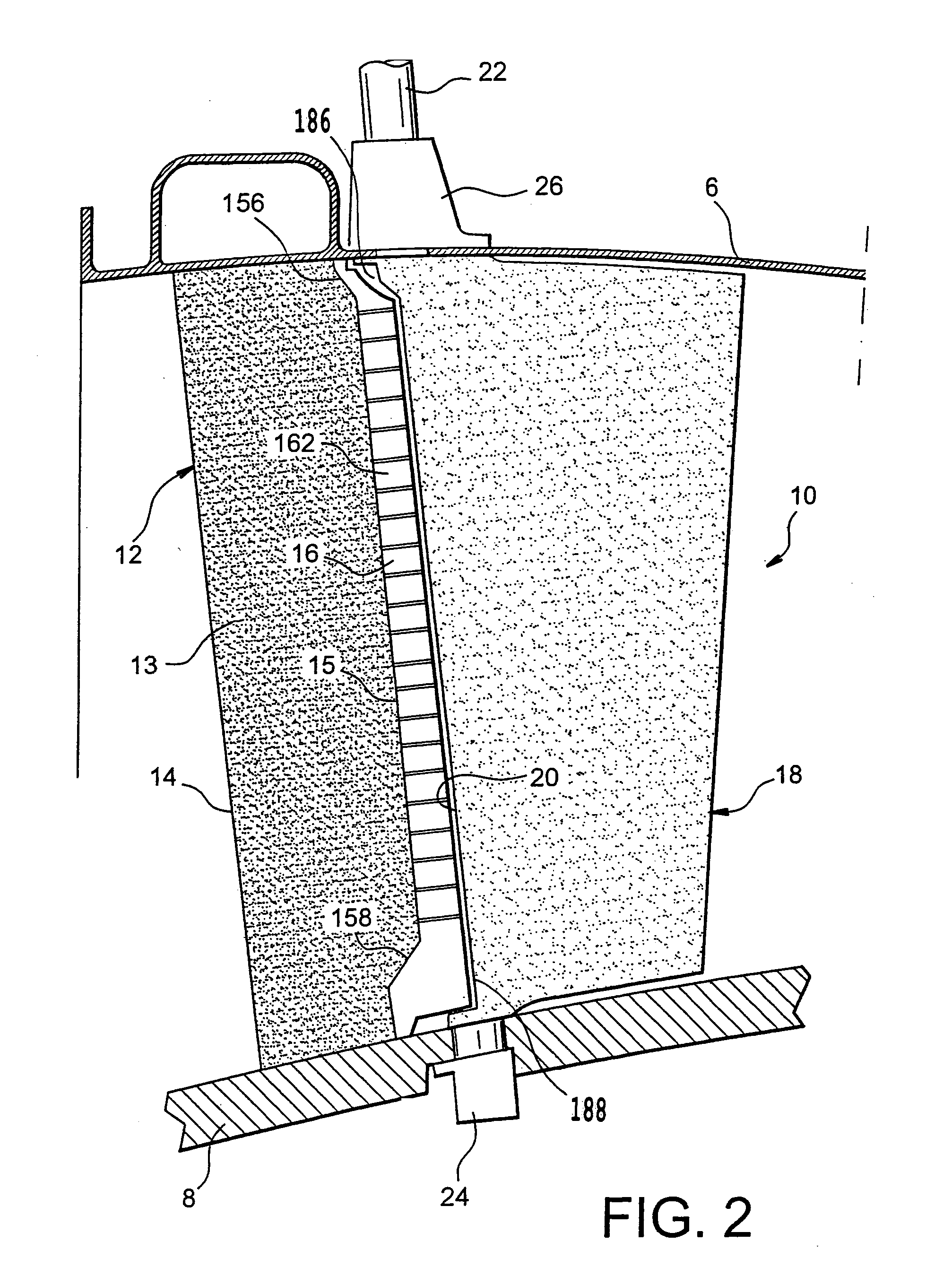
[0040]According to the de-icing system illustrated in FIG. 5:[0041]the branch 162 located on the intrados side of the trailing edge 16 of the fixed part 12, comprises at least one emission window 202 through which secondary air flows outside the hollow body 13 as indicated by the arrow 52,[0042]the branch 164 that is located on the extrados side of the trailing edge 16 of the fixed part 12, comprises at least one emission window 204 through which the secondary air flows outside the hollow body 13, as indicated by the arrow 54.

[0043]In the same way as in the first embodiment, the hot air passing through an emission window 202 located in the branch 162 on the intrados side of the fixed part 12, then passes along the intrados side of the mobile flap 18 as indicated by the arrow 62. The intrados side of the mobile flap 18 is thus heated directly by the convection effect. Furthermore, hot air passing through an emission window 204 located in the branch 164 on the extrados side of the fix...

first embodiment

[0050] illustrated in FIG. 7a, the geometry of the hollow areas 168 is such that the cross-section of the emission windows 202, 204 is constant and prismatic.

[0051]According to a second embodiment illustrated in FIG. 7b, the geometry of the hollow areas 168 is such that the cross-section of the emission windows 202, 204 is constant and inclined upwards in the direction of the hot air flow 58.

third embodiment

[0052] illustrated in FIG. 7c, the geometry of the hollow areas 168 is such that the cross-section of the emission windows 202, 204 is constant and inclined downwards in the direction of the hot air flow 58.


PUM


Abstract

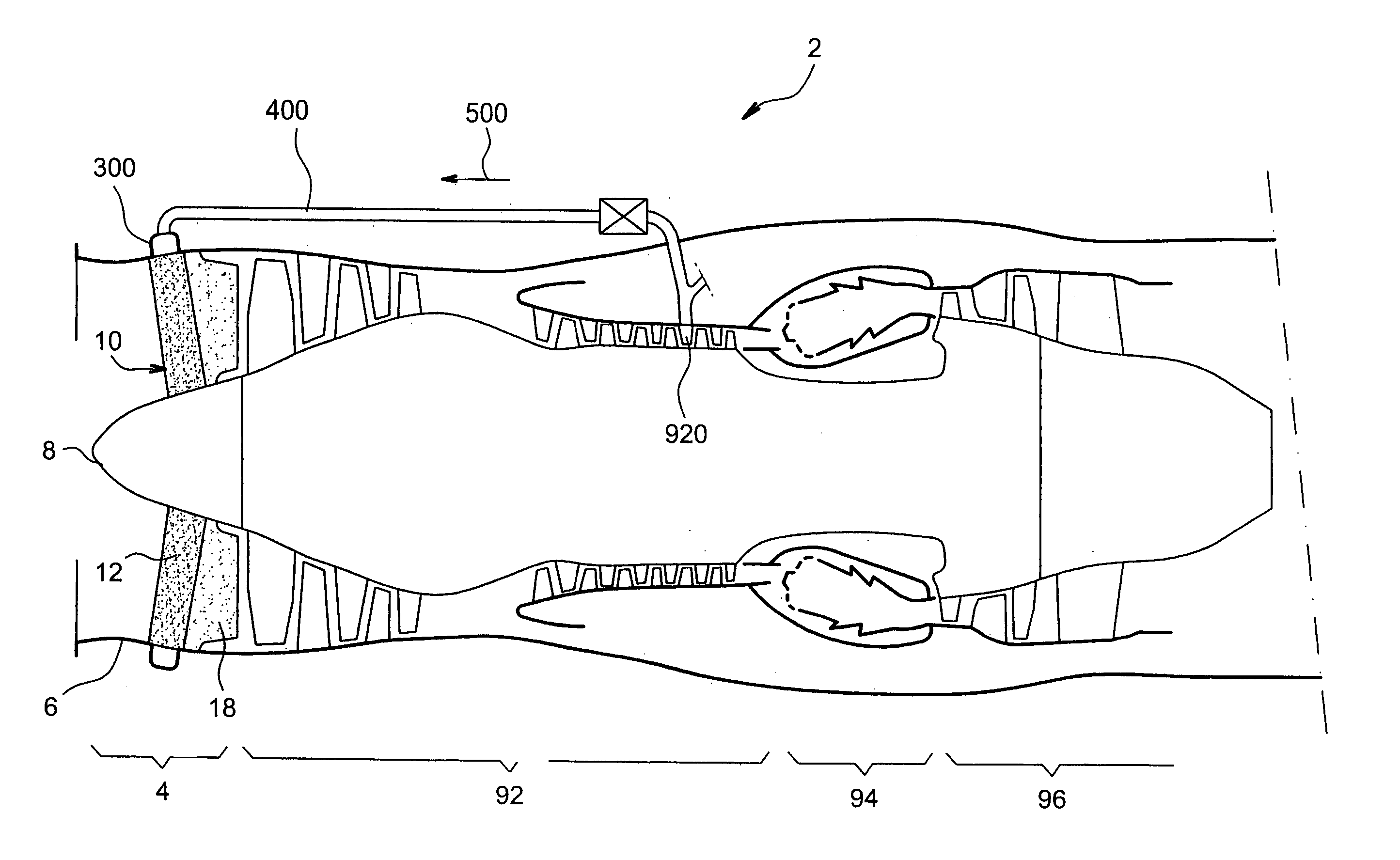
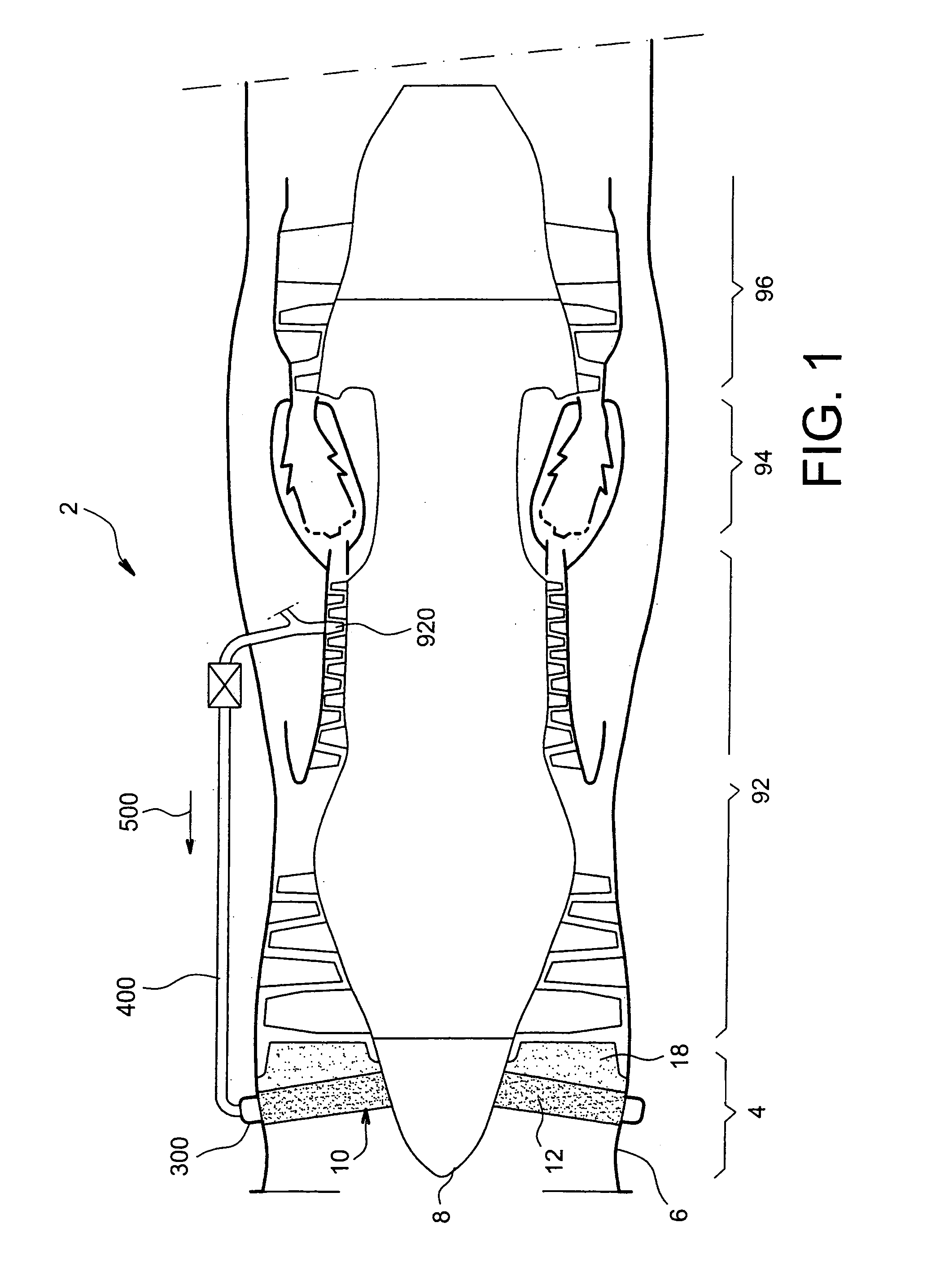
The de-icing device is intended for the vane (10) of the inlet guide wheel (4) of a turbojet (2), comprising a fixed part (12) arranged on the upstream side and a mobile flap (18) arranged on the downstream side, in which said fixed part (12) comprises a trailing edge (16) substantially in the shape of a “U”, with one of the branches (162) being located on the intrados side (I) and the other branch (164) being located on the extrados side (E). It comprises at least one emission window (202), oriented substantially along an upstream-downstream direction, and arranged along the branch (162) of the “U” located on the intrados side (I) of the trailing edge (16).The inlet guide wheel (4) vane (10) is equipped with at least such a de-icing device.The aircraft engine (2) comprises at least one vane (10) equipped with such a de-icing device.

Description

DESCRIPTION[0001]1. Technical Field[0002]This invention relates to the technical domain of de-icing devices for turbojet inlet guide wheels. It also relates to an inlet guide wheel vane equipped with such a de-icing device. It also relates to an aircraft engine equipped with such vanes.[0003]2. State of Prior Art[0004]For example document FR 2 607 188 describes turbojet inlet guide wheel vanes with variable pitch connecting an inlet casing to a central hub. Each of these vanes comprises a fixed part and a mobile flap. The fixed parts are structural parts arranged radially about the central hub and act as a support for the inlet casing. They are also called inlet casing arms. The mobile flaps are located on the downstream side of the fixed part with which they are associated and are articulated to it about a direction substantially radial from the central hub, by means of a radially internal pivot and a radially external pivot. The orientation of the mobile flaps provides a means of ...

Claims


Application Information

Patent Timeline
Patent Type & Authority Patents(United States)
IPC IPC(8): F02G3/00F01D5/14F01D17/16F02C7/047
CPCF01D5/146F01D17/162F02C7/047Y02T50/673Y02T50/672Y02T50/60
Inventor COURTOT, YANNICK JEAN ROGERMARLIN, FRANCOIS MARIE PAULDANIELO, JEAN ARMAND FRANCOIS
Owner SN DETUDE & DE CONSTR DE MOTEURS DAVIATION S N E C M A
Learn More