Vehicle axle beam and brake assembly

a technology of brake assembly and axle beam, which is applied in the direction of brakes, mechanically actuated drum brakes, actuators, etc., can solve the problems of cumbersome manufacturing, high cost, and large change requirements of current pneumatically actuated drum brake assemblies, and achieve the effect of convenient assembly

Inactive Publication Date: 2006-06-06
DANA CORP
View PDF18 Cites 19 Cited by
  • Summary
  • Abstract
  • Description
  • Claims
  • Application Information

AI Technical Summary

Benefits of technology

[0018]As illustrated in FIGS. 1 and 4, the present invention includes a mounting assembly that secures the pneumatic brake actuator cylinder 30 and rotary actuator 14 directly to the brake spider 5. The mounting assembly includes a mounting sleeve 40 for positioning and rotationally supporting the actuating shaft 16 therewithin. The mounting sleeve 40 may be of any length depending on the vehicle and applicable clearance space. The mounting sleeve is provided with a first mounting bracket 42 at one end, and a second mounting bracket 44 at the oth

Problems solved by technology

This conventional design renders current pneumatically actuated drum brake assemblies quite complex in manufacturing, cumbersome, expensive and

Method used


Image

  • Vehicle axle beam and brake assembly
  • Vehicle axle beam and brake assembly
  • Vehicle axle beam and brake assembly

Examples


Embodiment Construction

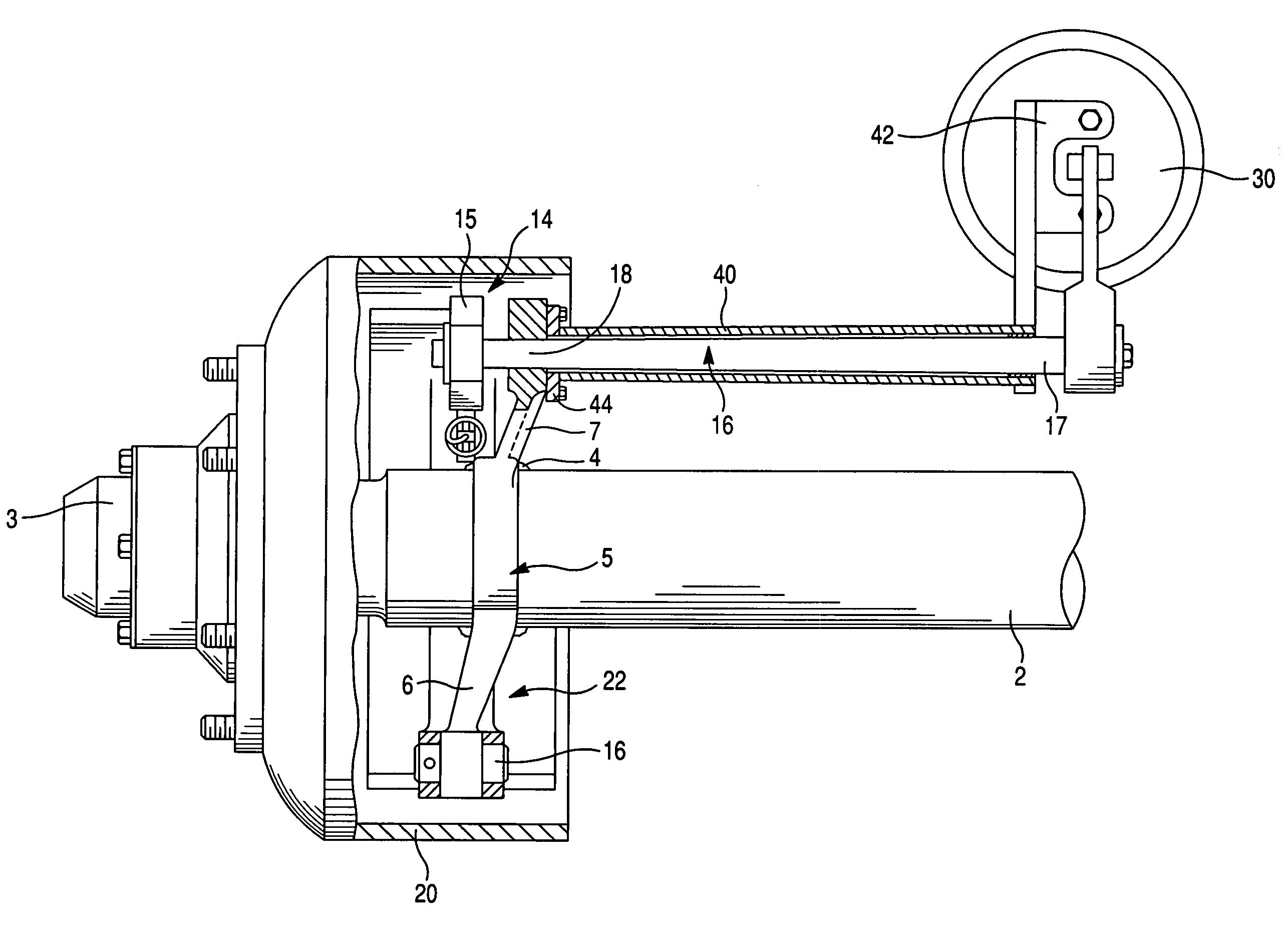
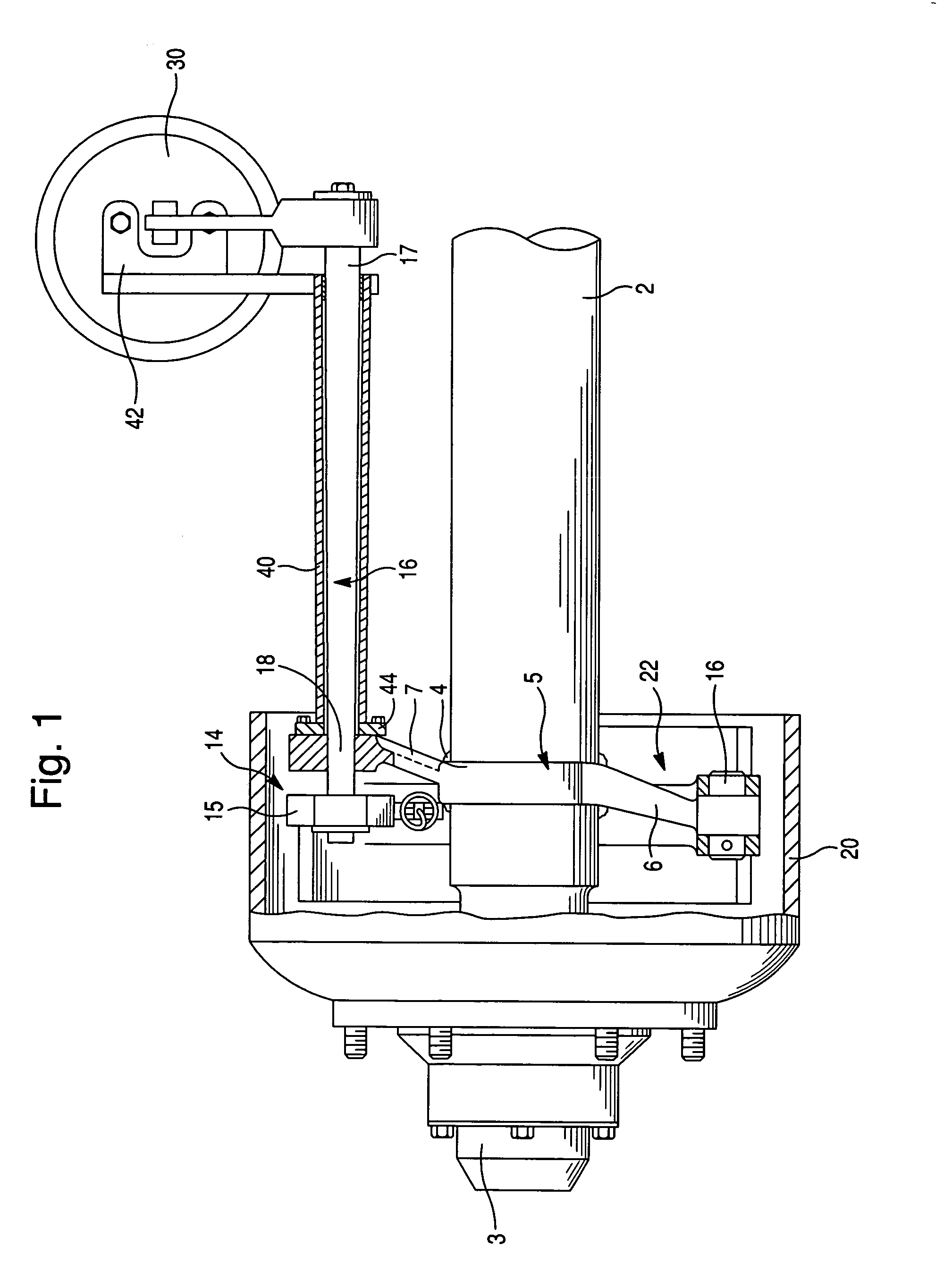
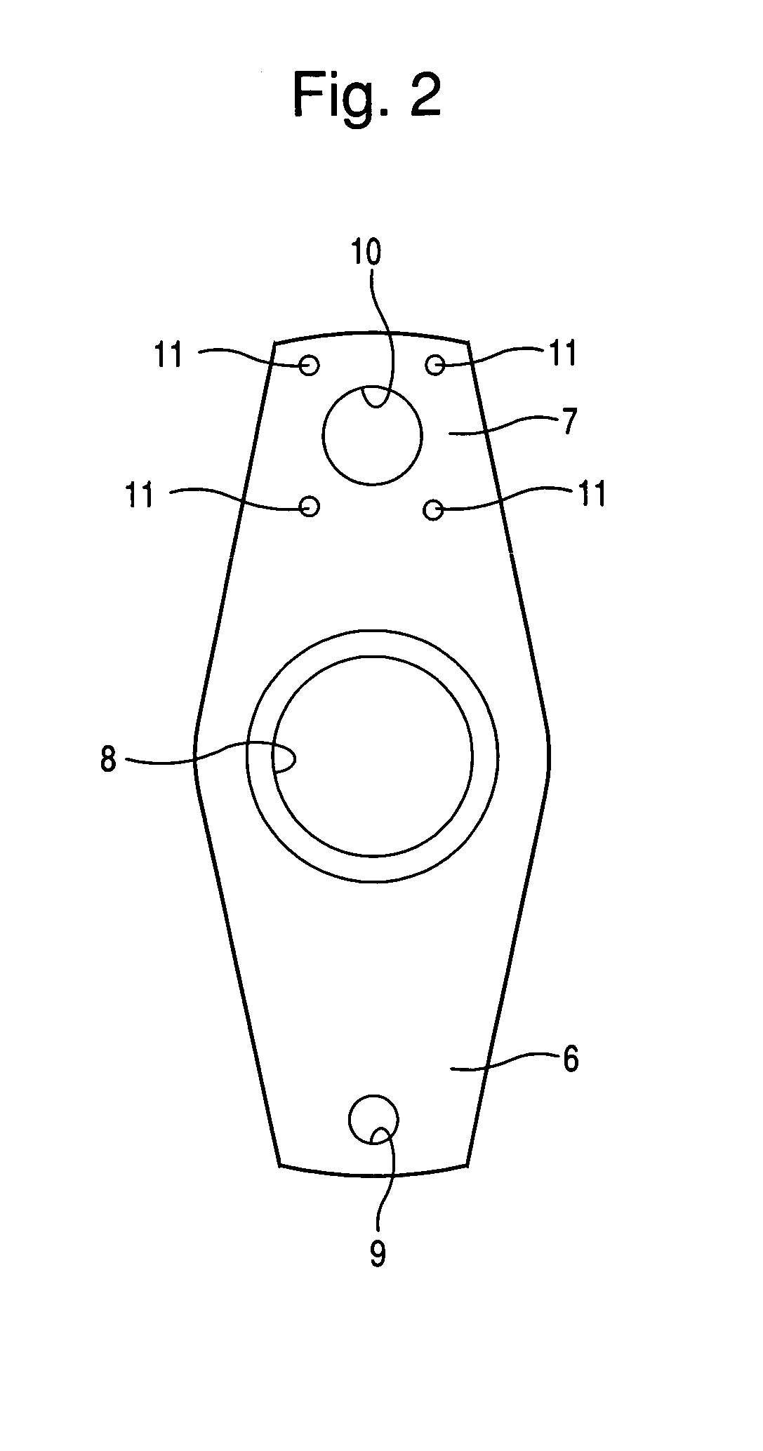
[0011]FIG. 1 of the drawings depicts a novel arrangement of a pneumatically actuated drum brake assembly of the present invention adapted to be utilized for heavy duty trucks. Reference numeral 2 defines an axle beam including a spindle 3 rotatably supporting a wheel (not shown). A brake spider 5 is non-removably secured to the axle beam 2, preferably by welding. The welding joint between the axle beam 2 and the brake spider 5 is indicated generally by reference numeral 4. The brake spider, illustrated in FIG. 2, comprises a pivoting end support plate 6 and an actuator support plate 7 extending generally opposite to the pivoting end support plate 6, and defines a central aperture 8 through which the axle beam 2 is positioned.

[0012]The brake assembly includes a brake drum 20 mounted to a wheel hub (not shown) which is rotatably mounted on the spindle 3. The brake assembly utilizes a pair of brake shoes 22 each including a pair of axially spaced webs 23.

[0013]In order to selectively m...


PUM


Abstract

An improved axle beam and self-contained drum brake assembly, particularly for heavy duty trucks, is disclosed. The assembly includes a brake spider and actuating members mounted thereto via a mounting assembly comprising a mounting sleeve attached to the brake spider by means of a second mounting bracket, and a first mounting bracket securing a pneumatic brake actuator cylinder to the mounting sleeve. A brake actuating camshaft is positioned and rotationally supported therewithin. The disclosed brake assembly allows for numerous variations of axle beam and suspension arrangements.

Description

BACKGROUND OF THE INVENTION[0001]1. Field of the Invention[0002]The present invention relates to a drum brake arrangement for motor vehicles in general, and particularly to a novel arrangement of various components of a pneumatically actuated drum brake assembly for rear axles of heavy duty trucks.[0003]2. Description of the Prior Art[0004]Pneumatically actuated drum brakes are well known in the prior art. Typically, a pneumatically actuated drum brake assembly includes a brake spider bolted to a flange on an axle beam. The brake spider is adapted to support a pair of brake shoes. A brake actuator shaft provided with an S-cam at one end and a pneumatic actuator at the other end, is normally supported on the axle beam by at least one bracket welded to the axle beam. This conventional design renders current pneumatically actuated drum brake assemblies quite complex in manufacturing, cumbersome, expensive and require a great deal of changes in the current production in order to accommo...

Claims


Application Information

Patent Timeline
IPC IPC(8): F16D51/00F16D51/22F16D65/09F16D65/14F16D65/22
CPCF16D51/22F16D65/09F16D65/22F16D2125/56F16D2051/003F16D2125/30
Inventor JONES, JEFFREY LEEBROOKS, DANIEL E.CLARK, JAMES ROBERTMEYER, CARL HEINZ
Owner DANA CORP
Why Eureka
Try Eureka