Liquid discharge head cartridge

a liquid discharge and cartridge technology, applied in printing and other directions, can solve the problems of reducing recording performance, inability to prevent deformation, and inability to remove a bubble in the ink channel, and achieve excellent recording characteristics

Active Publication Date: 2006-06-06
CANON KK
View PDF8 Cites 6 Cited by
  • Summary
  • Abstract
  • Description
  • Claims
  • Application Information

AI Technical Summary

Benefits of technology

[0017]It is an object of the present invention to provide a liquid discharge head cartridge, in which a liquid discharge head and an ink tank are integrated, capable of assuredly supplying the liquid discharge head with a liquid even if a bubble is generated within an ink channel of the liquid discharge head cartridge, while maintaining excellent recording characteristics even in a configuration where the above-described light recovery or no recovery is adopted.

Problems solved by technology

However, in the conventional ink-jet recording head, when adopting light recovery where light recovery processing is performed only for clogging of an orifice, or no recovery in which no recovery processing is performed, removal of a bubble within the ink channel is not performed.
Thus, there the possibility remains that the bubble can block the flow of ink, resulting in decreased recording performance.
However, when the diameter of the cross section of the ink channel (i.e., liquid introducing channel) of the ink-jet recording cartridge is simply increased, the positions to provide struts for supporting the filter are limited, resulting in an inability to prevent deformation (e.g., a recess) in the direction of the thickness of the filter.

Method used


Image

  • Liquid discharge head cartridge
  • Liquid discharge head cartridge
  • Liquid discharge head cartridge

Examples


first embodiment

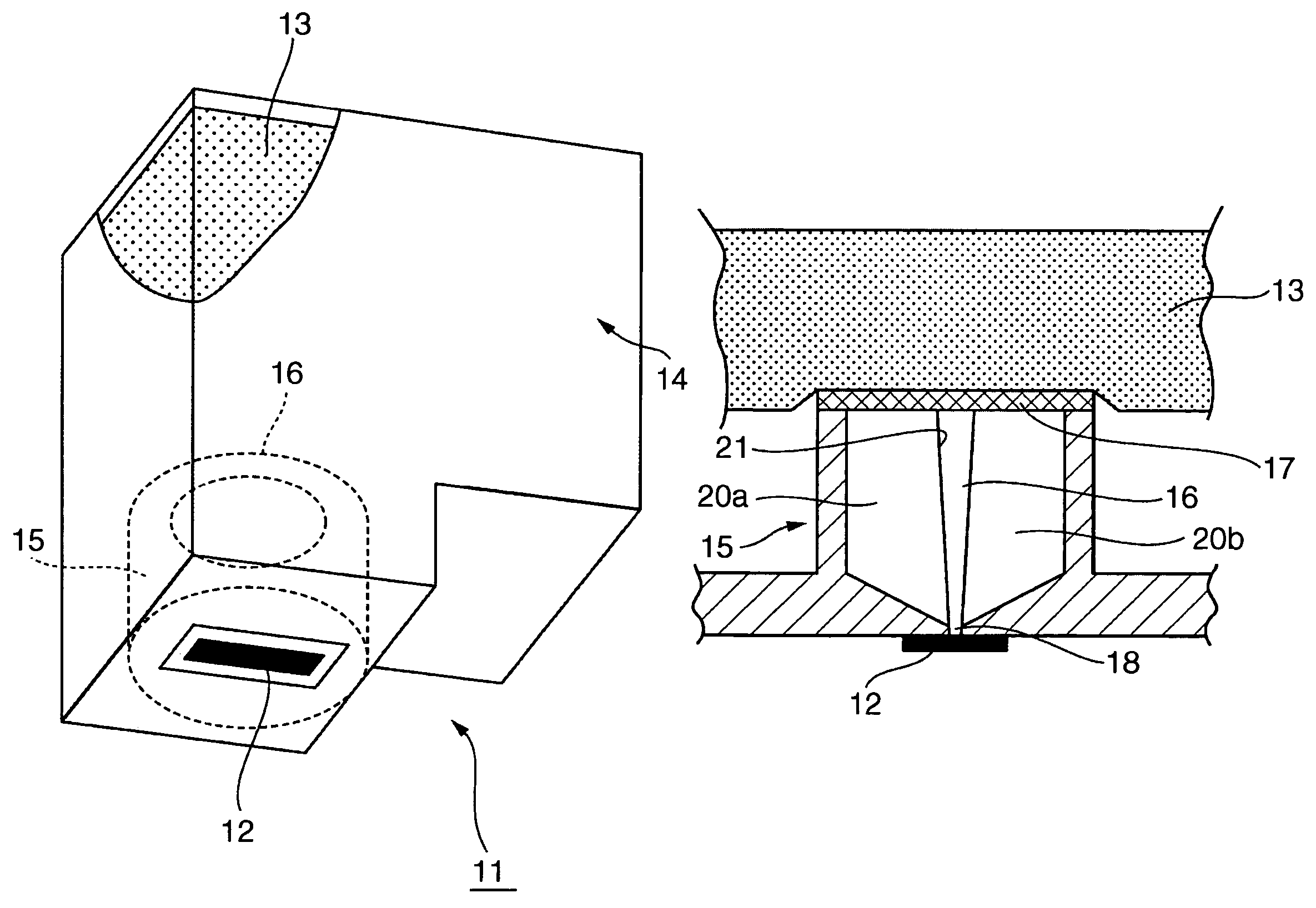
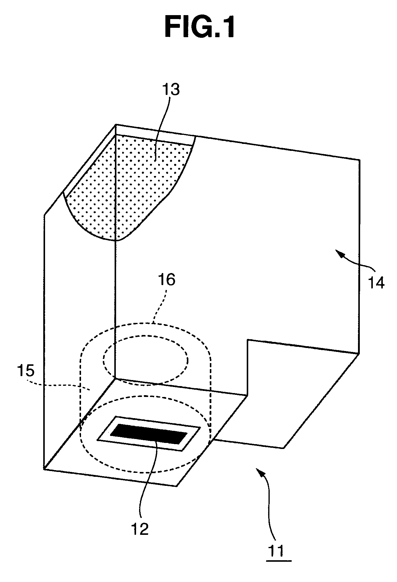
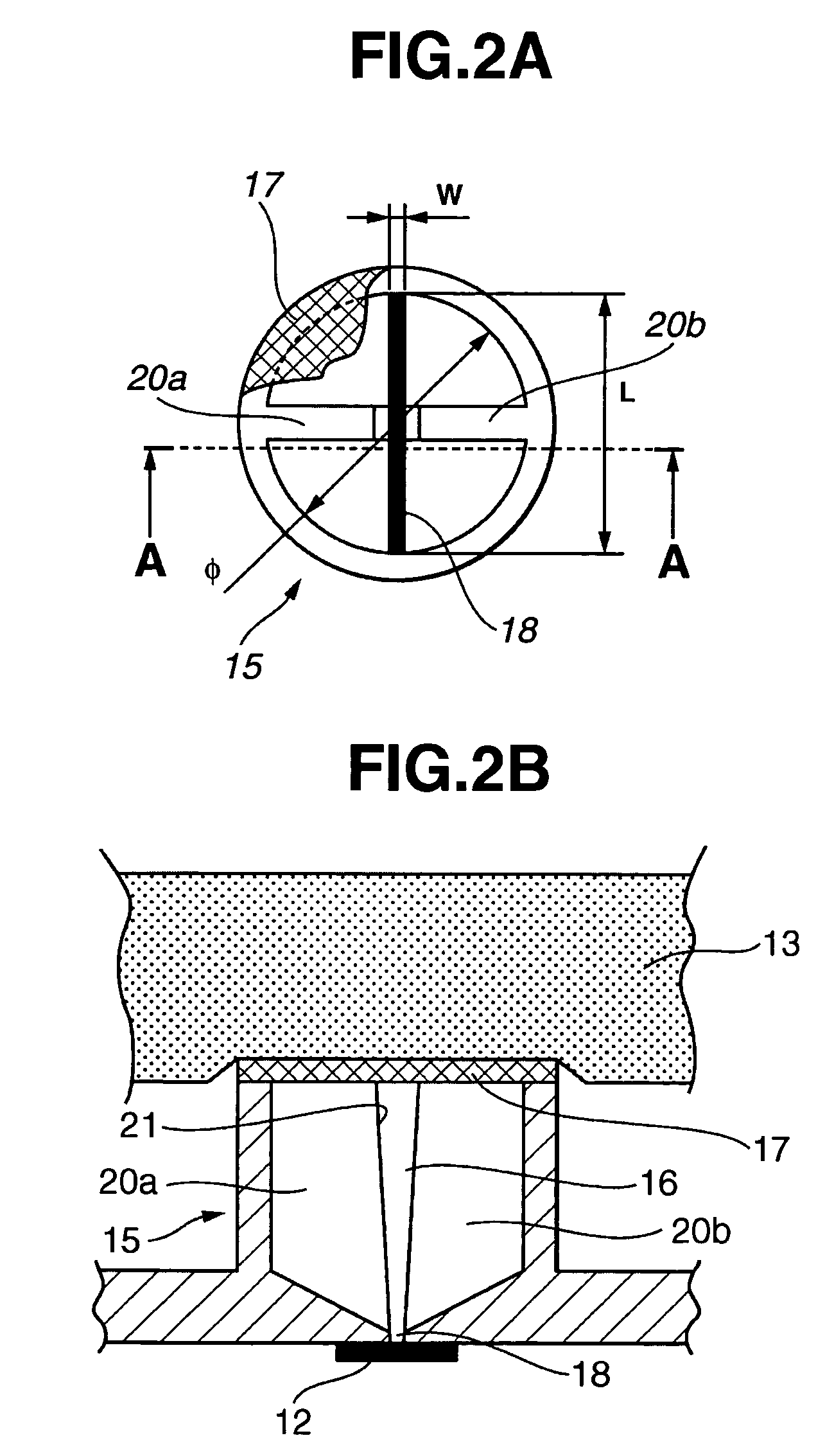
[0035]FIG. 1 is a schematic perspective view illustrating an ink-jet recording cartridge according to a first embodiment of the present invention. FIGS. 2A and 2B are diagrams illustrating an ink introducing unit of the ink-jet recording cartridge shown in FIG. 1. FIG. 2A is a plan view in which the ink introducing unit is seen from a filter side, i.e., an ink introducing direction, toward an opening; and FIG. 2B is a cross-sectional view taken along line A—A shown in FIG. 2A.

[0036]As shown in FIG. 1, an ink-jet recording cartridge 11 includes an ink-jet recording head 12 for discharging ink (hereinafter referred to as a “recording head”), and an ink-tank unit 14 incorporating an ink absorber 13 for holding ink to be supplied to the recording head 12. Within the ink-jet recording cartridge 11, an ink introducing unit 15 for supplying the recording head 12 with ink from the ink absorber 13 holding ink, via an ink channel 16 is provided between the recording head 12 and the ink absorb...

second embodiment

[0047]FIG. 4 is a schematic perspective view illustrating a principal portion of a recording apparatus including an ink-jet recording cartridge according to a second embodiment of the present invention. Since the ink-jet recording cartridge of the second embodiment has the same basic configuration as the ink-jet recording cartridge 11 of the first embodiment, the same components as those in the first embodiment are indicated by the same reference numerals, and further description thereof will be omitted.

[0048]As shown in FIG. 4, two ink-jet recording cartridges 31 of different types are mounted on a carriage 5 included in an ink-jet recording apparatus 1. The ink-jet recording cartridges 31 include a black-ink cartridge 31a mounting black ink, and a color-ink cartridge 31b mounting color ink liquids, such as yellow, magenta, and cyan ink liquids.

[0049]The carriage 5 is reciprocatable in the Y direction, and performs recovery processing for an ink-jet recording head 12 of the ink-jet...

third embodiment

[0063]FIGS. 7A and 7B are diagrams illustrating an ink introducing unit of an ink-jet recording cartridge according to a third embodiment of the present invention. FIG. 7A is a plane view in which the ink introducing unit is seen from a filter side, i.e., an ink introducing direction, toward an opening; FIG. 7B is a cross-sectional view taken along line A—A shown in FIG. 7A. Since the ink-jet recording cartridge of the third embodiment has the same basic configuration as the ink-jet recording cartridge 11 of the first embodiment, the same components as those in the first embodiment are indicated by the same reference numerals, and further description thereof will be omitted.

[0064]As shown in FIGS. 7A and 7B, within the ink-jet recording cartridge, an ink introducing unit 45 for supplying a recording head 12 with ink from an ink absorber 13 for holding ink, via an ink channel 46 is provided between the recording head 12 and the ink absorber 13.

[0065]The ink introducing unit 45 has th...


PUM


Abstract

A liquid discharge head cartridge can assuredly supply a liquid discharge head with a liquid even when a bubble is generated within a liquid channel, and maintain excellent recording characteristics even in a configuration in which light recovery or no recovery is adopted. The cartridge includes a slit-shaped opening provided at an ink channel facing an ink-jet recording head, a filter provided at an ink introducing unit so as to contact an ink absorber, and ribs for supporting the filter that extend from an inner wall of the ink introducing unit to a substantially central portion of the filter.

Description

BACKGROUND OF THE INVENTION[0001]1. Field of the Invention[0002]The present invention relates to a liquid discharge head cartridge for recording characters, images and the like on a recording sheet or the like by discharging ink or the like.[0003]2. Description of the Related Art[0004]The configurations of ink-jet recording heads for improving the recording speed of an ink-jet recording apparatus have been disclosed as the shapes of ink introducing units of conventional ink-jet recording cartridges, particularly ink-jet recording heads (e.g., Japanese Patent Application Laid-Open (Kokai) No. 2002-137410).[0005]Ink-jet recording heads of this type have a configuration for maintaining an excellent state of contact between a filter and a pressing member contacting the filter in order to stabilize an ink supply property for the ink-jet recording head, because the flow rate of supplied ink is large.[0006]The above-described conventional ink-jet head will now be described with reference t...

Claims


Application Information

Patent Timeline
Patent Type & Authority Patents(United States)
IPC IPC(8): B41J2/175
CPCB41J2/17513
Inventor AMMA, HIROMASATAKAHASHI, WATARUHAYASHI, HIROKIOGAWA, MASASHIKOTAKI, YASUO
Owner CANON KK
Why Eureka
Try Eureka