Optical Recording Medium

a recording medium and optical technology, applied in mechanical recording, recording information storage, instruments, etc., can solve the problems that the data recorded in the optical medium may not last a long time, and achieve the effects of low melting point, low cost, and reduced laser power required to generate the recording mark

Inactive Publication Date: 2008-08-21
LG ELECTRONICS INC
View PDF6 Cites 2 Cited by
  • Summary
  • Abstract
  • Description
  • Claims
  • Application Information

AI Technical Summary

Benefits of technology

[0014]Preferably, the information recording layer comprises one or more first information recording layers and one or more second information recording layers, and the first information recording layers and the second information recording layers are alternately laminated such that the number of contacting surfaces between the first information recording layers and the second information recording layers is equal to or greater than two. When there are two or more contact surfaces, since reactive area between recording material of the two information recording layers is increased, the recording mark is easily generated in the thickness direction of the optical recording medium.
[0015]In order to maintain a predetermined reflectance of the recording marks generated in the information recording layers, the a thickness of the information recording layer is equal to or greater than 90 Å and less than 200 Å. Moreover, the information recording layer further comprises a recording sensitivity acceleration layer containing one or more elements selected from a group of Sn, Yn, Pb, Bi, Ti, Te, Se, S, Al, Ga, Ge, Cd, I, and In. The recording sensitivity acceleration layer is laminated to contact any one of surfaces of the first information recording layer through which the laser beam firstly enters and the surface thereof near the substrate. Preferably, the recording sensitivity acceleration layer is laminated to contact any one of surfaces of the second information recording layer through which the laser beam firstly enters and the surface thereof near the substrate. Since the materials contained in the recording sensitivity accelerating layer have low melting points, the materials react before the other materials contained in the respective information recording layers when the laser beam is projected thereonto. At this time, since latent heat caused by the reactions supplies heat required in the reactions in the information recording layers, the laser power required to generate the recording mark can be reduced.
[0016]The optical recording medium further includes a dielectric layer laminated to contact at least one of surfaces of the first information recording layer through which the laser beam firstly enters and the surface thereof near the substrate. The dielectric layer prevents the substrate or a plastic cover sheet from damage due to increased temperature in the information recording layers according to the position thereof, or emits heat generated in the information recording layer at a proper rate to properly adjust thermal equilibrium of the information recording layers.

Problems solved by technology

However, when the organic material is used in forming the information recording layer, data recorded in the optical medium may not last for a long time.

Method used


Image

  • Optical Recording Medium
  • Optical Recording Medium
  • Optical Recording Medium

Examples


Embodiment Construction

[0039]Reference will now be made in detail to the preferred embodiments of an optical recording medium of the present invention, examples of which are illustrated in the accompanying drawings.

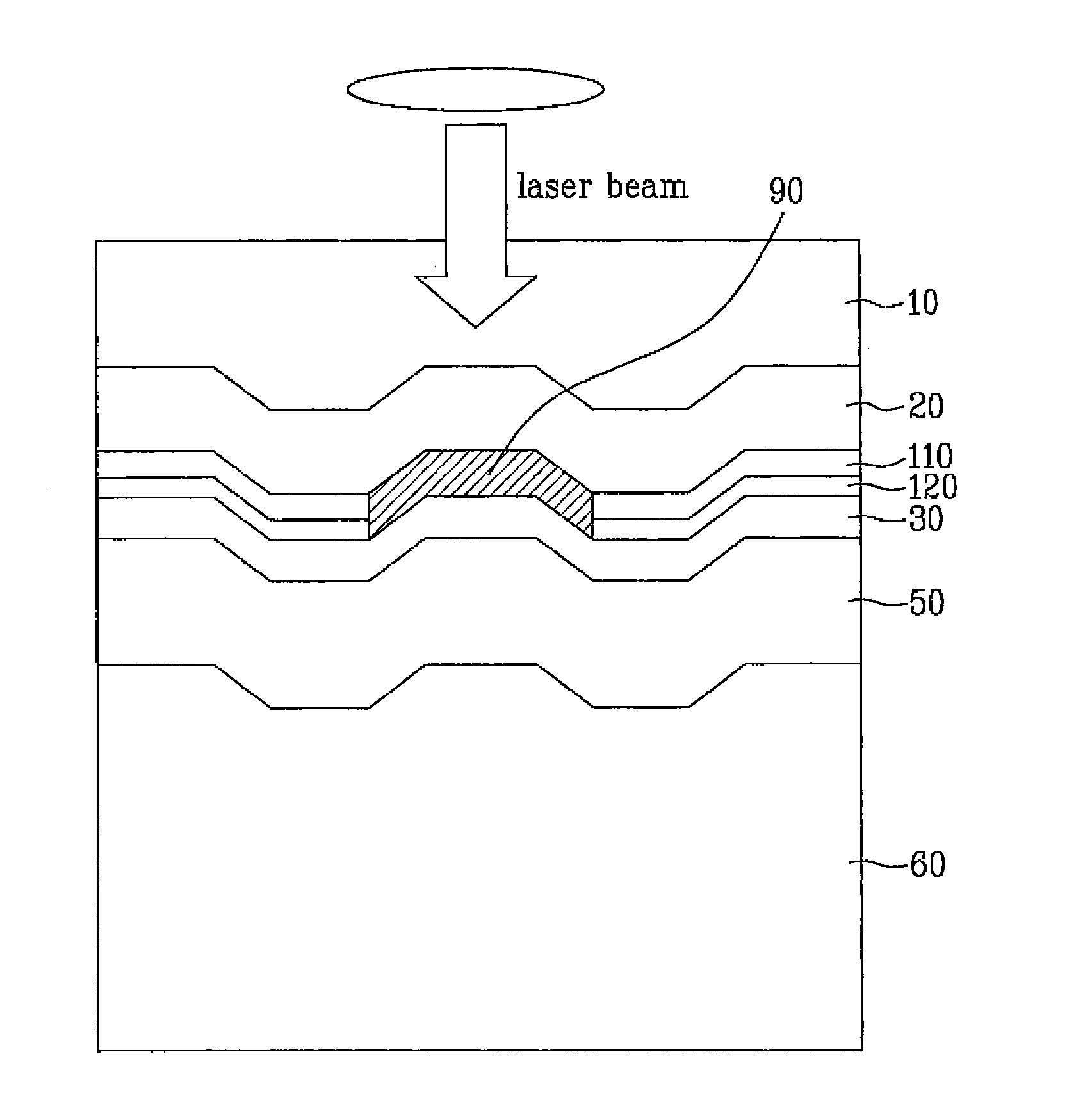
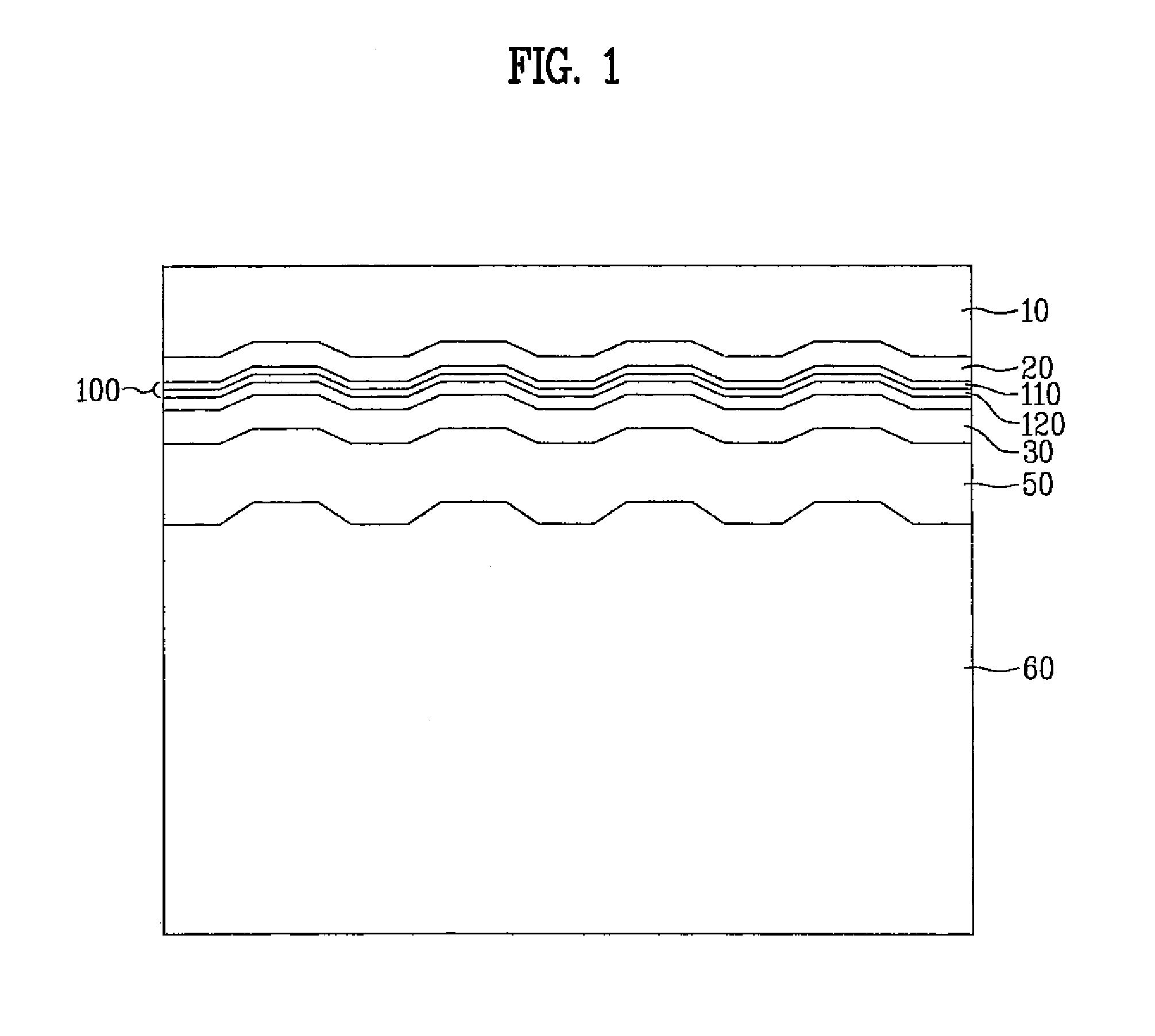
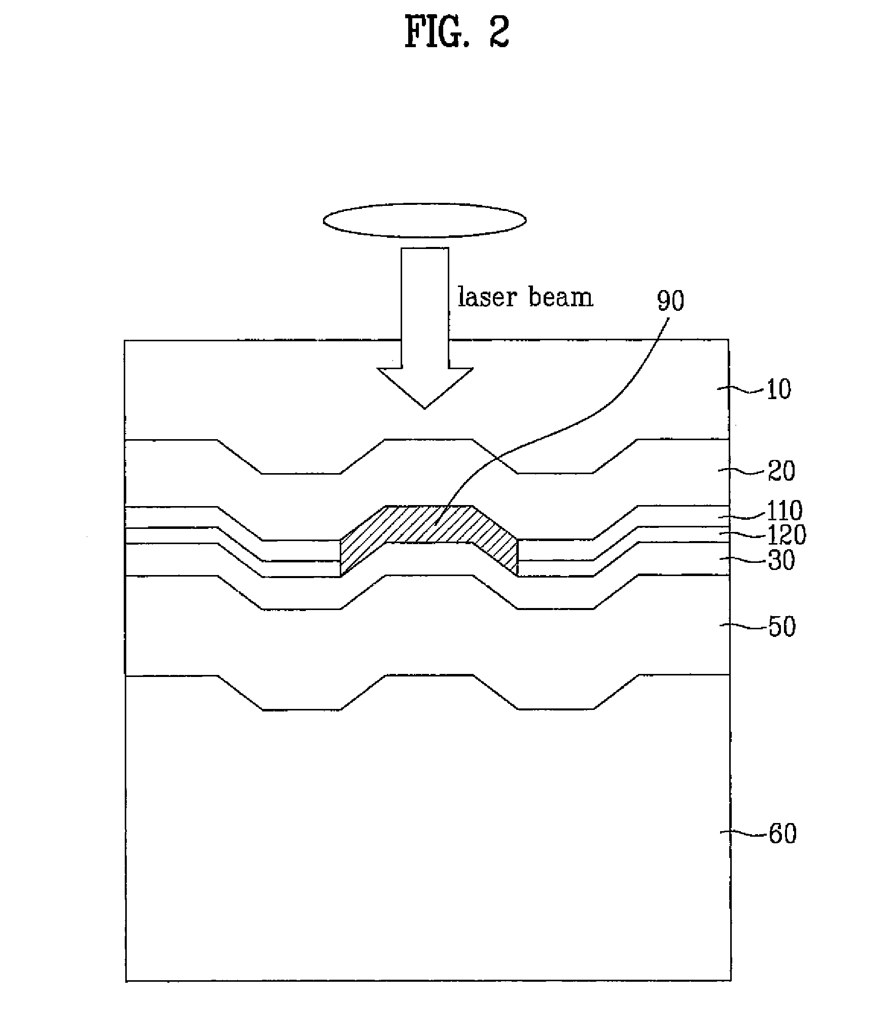
[0040]Referring to FIG. 1, a structure of an optical recording medium according to a preferred embodiment of the present invention will be described as follows. The optical recording medium according to the preferred embodiment of the present invention includes a substrate 60, a reflective layer 50, and an information recording layer 100. Moreover, the optical recording medium preferably further includes an optical transmission layer 10 and dielectric layers 20 and 30. The information recording layer includes a first information recording layer 110 and a second information recording layer 120.

[0041]The substrate 60 supports a physical shape of the optical recording medium according to the preferred embodiment of the present invention. As the substrate 60, ceramic, glass, or resin is usually use...


PUM

PropertyMeasurementUnit
thicknessaaaaaaaaaa
thicknessaaaaaaaaaa
thicknessaaaaaaaaaa

Abstract

An optical recording medium records information in a mechanism of generating new material, having reflectance different from that of others in information recording layer, when laser beam is projected thereonto. The optical recording medium includes a substrate, and a reflective layer positioned on the substrate to reflect an entering laser beam and having an information recording layer. The information recording layer includes a first information recording layer containing one or more elements selected from a group of Si, Ge, and Sb, and a second information recording layer containing one or more elements selected from a group of Si, Sb, Te, and Al. Data can be recorded in high density and the optical recording medium provides high recording stability and recording sensitivity.

Description

TECHNICAL FIELD[0001]The present invention relates to an optical recording medium, and more particularly, to an optical recording medium having a high recording stability and a data recording density.BACKGROUND ART[0002]A multimedia age when video signals containing a motion picture and a still image, audio signal, and computer data are integrally processed has come, and simultaneously package media such as a compact disc (CD), a digital versatile disc (DVD), and the like are popularized far and wide. Recently, attempts are vigorously carried out to apply an optical recording medium to a recording medium of a mobile phone, a digital camera, broadcasting, movie, or the like. In new generation media, this trend would be stronger.[0003]The optical recording medium is grouped into a read-only-memory (ROM) type optical recording medium, a recordable type optical recording medium to record information only once, and a rewritable type optical recording medium to write and erase information...

Claims


Application Information

Patent Timeline
Patent Type & Authority Applications(United States)
IPC IPC(8): G11B7/26
CPCG11B7/24038G11B7/243G11B7/2433G11B2007/24316G11B2007/2431G11B2007/24312G11B2007/24314G11B2007/24308
Inventor LEE, SEUNG YOONSEO, HUN
Owner LG ELECTRONICS INC
Why Eureka
Try Eureka