Fluid mixing system

a fluid mixing and fluid technology, applied in the direction of instruments, sealing/packing, borehole/well accessories, etc., can solve the problems of insufficient density measurement, ineffective slurries using low density solid materials, and insufficient density measurement to control the amount of solid materials added to the necessary accuracy

Inactive Publication Date: 2006-06-06
SCHLUMBERGER TECH CORP
View PDF17 Cites 36 Cited by
  • Summary
  • Abstract
  • Description
  • Claims
  • Application Information

AI Technical Summary

Benefits of technology

[0009]The present invention seeks to provide a mixing system which avoid the problem of density measurement described above.

Problems solved by technology

This measurement method is sensitive to human error in level reading, switching from on tank to another and tank exact capacity.
Even more an error in the number of tanks counted can have many consequences (over displacement can result in wet shoe, under displacement can result in no pressure bump or cement left in the casing).
While this system is effective for slurries using materials of much higher density than water, it is not effective for slurries using low density solid materials, especially when the density of the solids is close to that of water.
In such cases, a density measurement is not sensitive enough to control the amounts of solid material added to the necessary accuracy.

Method used


Image

  • Fluid mixing system
  • Fluid mixing system
  • Fluid mixing system

Examples


Embodiment Construction

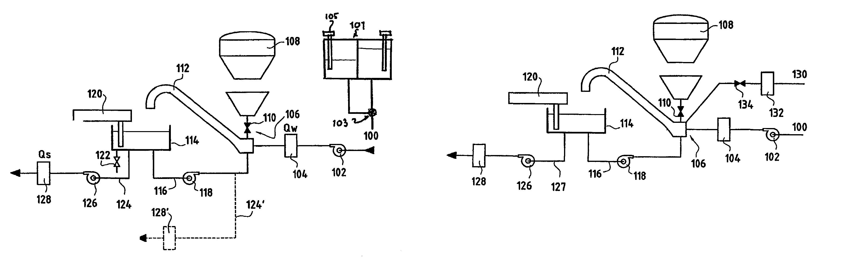
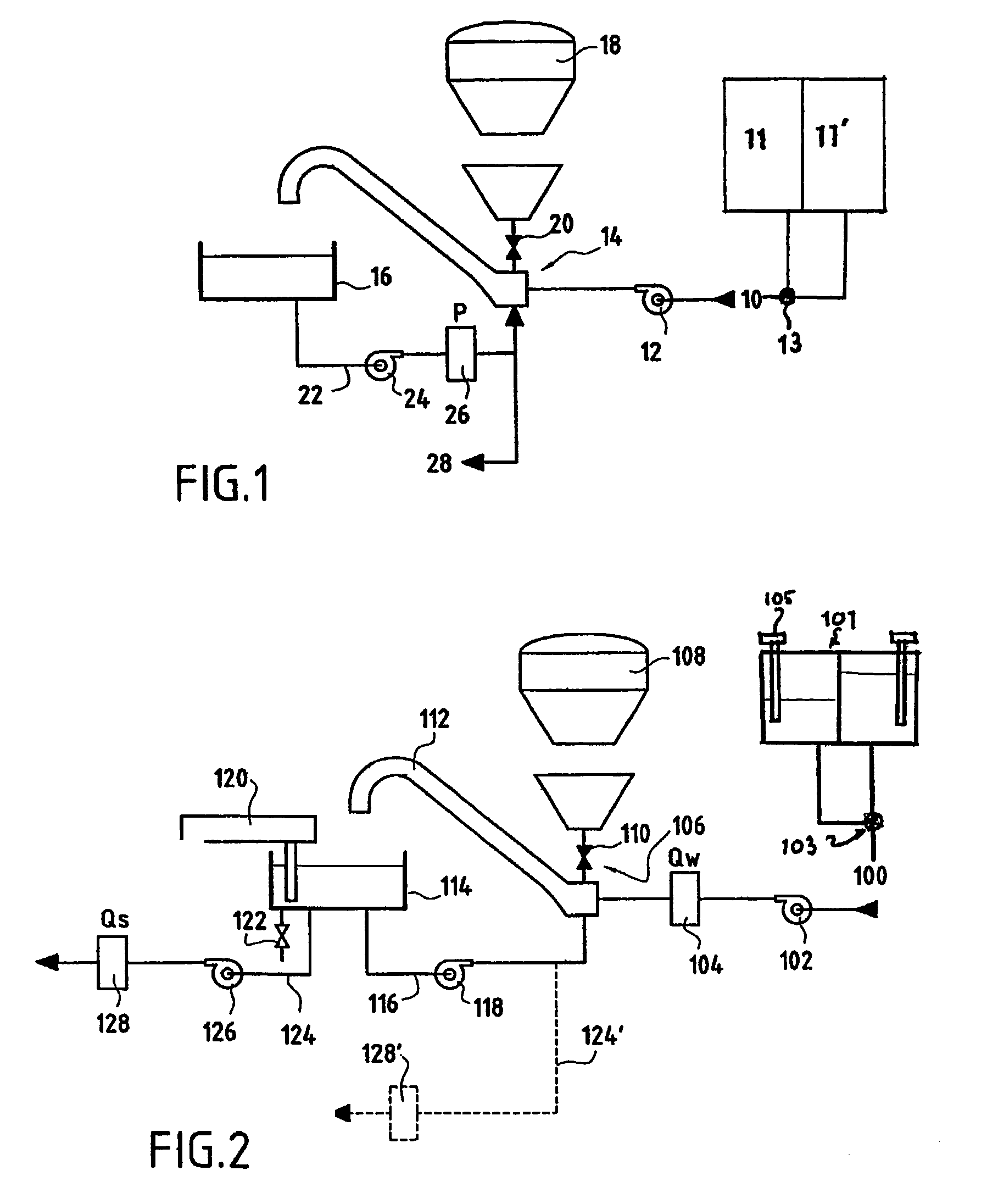
[0030]The system shown in FIG. 2 is used for the continuous mixing of cement for oil well cementing operations and comprises a supply of mix water 100 feeding, via a pump 102 and a flow meter 104 to a mixing system 106.

[0031]The supply of mix water comprises a pair of displacement tanks 101, each having a separate output connected to a valve 103 which supplies the pump 102. Level sensors 105 are included in each displacement tank 101 for determining the amount of water supplied to the pump 102. In another version (not shown), the level sensors are omitted. The amount of water supplied is determined in the manner described below.

[0032]The mixing system 106 also receives solid materials from a surge can 108 (or alternatively directly from a surge can) which are admitted through a valve 110. The mixed solid and liquid materials are delivered through a feed pipe 112 to a mixing tub 114. The mixing tub 114 has a first outlet 116 connected to a recirculation pump 118 which feeds the slurr...


PUM

PropertyMeasurementUnit
weightaaaaaaaaaa
flow rateaaaaaaaaaa
liquidaaaaaaaaaa

Abstract

A method for continuously mixing a borehole fluid such as cement includes using a measurement of the solid fraction of a cement slurry as it is being mixed to determine the ratio of the solid and liquid components to be added to the slurry. A system for mixing the includes a liquid material (water) supply including a flow meter; a solid material (cement) supply; a mixer which receives the liquid and solid materials and includes an output for delivering materials from the mixer to a delivery system; a device for measuring the amount of material in the mixer, and a flow meter in the output; wherein measurements from the flow meters and the device for measuring the amount of material in the mixer are used to control the amount of solid and / or liquid material added to the mixer.

Description

[0001]This is application is a 371 of PCT / EP01 / 11483 filed Oct. 4, 2001 which is a continuation application of U.S. application Ser. No. 09 / 726,784 filed Nov. 29, 2000, now U.S. Pat. No. 6,491,421.FIELD OF INVENTION[0002]The present invention relates to a system for mixing fluids containing solid and liquid materials such as cement. In particular the invention provides a system for the continuous mixing of cements or other fluids used in the drilling, completion or stimulation of boreholes such as oil or gas wells.BACKGROUND OF THE INVENTION[0003]When a well such as an oil or gas well has been drilled, it is often desired to isolate the various producing zones form each other or from the well itself in order to stabilise the well or prevent fluid communication between the zones or shut off unwanted fluid production such as water. This isolation is typically achieved by installing a tubular casing in the well and filling the annulus between the outside of the casing and the wall of t...

Claims


Application Information

Patent Timeline
Patent Type & Authority Patents(United States)
IPC IPC(8): B28C7/04B01F3/12B01F5/10B01F15/00B01F15/04B28C7/02E21B21/06E21B33/13G05D11/02G05D11/13
CPCB01F3/1271G05D11/135B01F15/00123B01F15/00136B01F15/00149B01F15/00155B01F15/00194B01F15/00207B01F15/0022B01F15/00233B01F15/00344B01F15/0445B28C7/022E21B21/062E21B33/13G05D11/132B01F5/106B01F2215/0047B01F2215/0081B01F2215/0409B01F23/59B01F25/53B01F35/21112B01F35/2111B01F35/20B01F35/2112B01F35/2117B01F35/2134B01F35/213B01F35/2132B01F35/2211B01F35/881B01F2101/28B01F2101/49B01F35/21
Inventor RONDEAU, JOELVIGNEAUX, PIERRE
Owner SCHLUMBERGER TECH CORP
Why Eureka
Try Eureka