
Stop stick deployment device and method

a technology stop stick, which is applied in the field of dispensing and roadway treatment arts, can solve the problems of police personnel being in the typical placement of tire deflation device manually, and the danger of being struck by the fleeing vehicl

Inactive Publication Date: 2006-06-06
KEITH BRETT +2
View PDF6 Cites 21 Cited by
  • Summary
  • Abstract
  • Description
  • Claims
  • Application Information

AI Technical Summary

Benefits of technology

[0015]Importantly, the deployment system enables a police officer to remain inside his vehicle and to deploy stop sticks while the police vehicle is moving at a high rate of speed.
[0017]One use of the system and method includes the disabling of a vehicle being driven by a terrorist. The design thus has utility for counter-terrorism activities.

Problems solved by technology

One problem in the art has been that the tire deflation devices are typically manually placed upon a roadway by police personnel.
Such personnel are thus placed in possible danger since they are required to leave the safety of a police vehicle.
That is, the police personnel may be in danger of being struck by the fleeing vehicle, by the occupants of the fleeing vehicle or by other innocent bystander vehicles in the area.

Method used


Image

  • Stop stick deployment device and method
  • Stop stick deployment device and method
  • Stop stick deployment device and method

Examples


Embodiment Construction

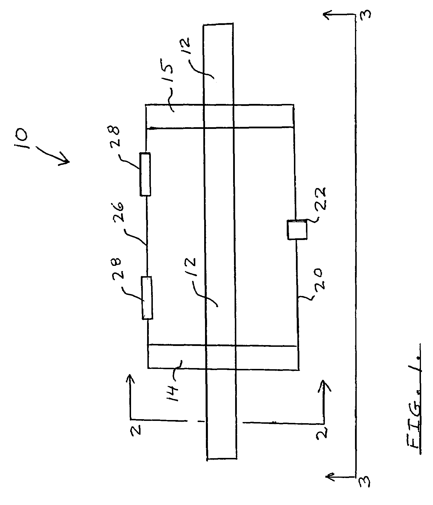
[0023]As shown in FIG. 1, the deployment system 10 includes a top bar 12 which is of sufficient strength to be mounted to a vehicle as will be further described.

[0024]Mounted to the top bar 12 is a left bracket 14 and a right bracket 15.

[0025]As further indicated in the top view of FIG. 1, a locking element 22 is positioned on a lock bracket 20.

[0026]A hinge bracket 26 serves to support hinge elements 28 which are attached to a gate to be further described.

[0027]In the embodiment shown, it is contemplated that the length of top bar 12 would be on the order of forty two inches.

[0028]The spacing between the left bracket 14 and the right bracket 15 would be on the order of twenty seven inches. The length of the bracket portions shown in FIG. 1 is on the order of nine inches. These dimensions will vary for different applications.

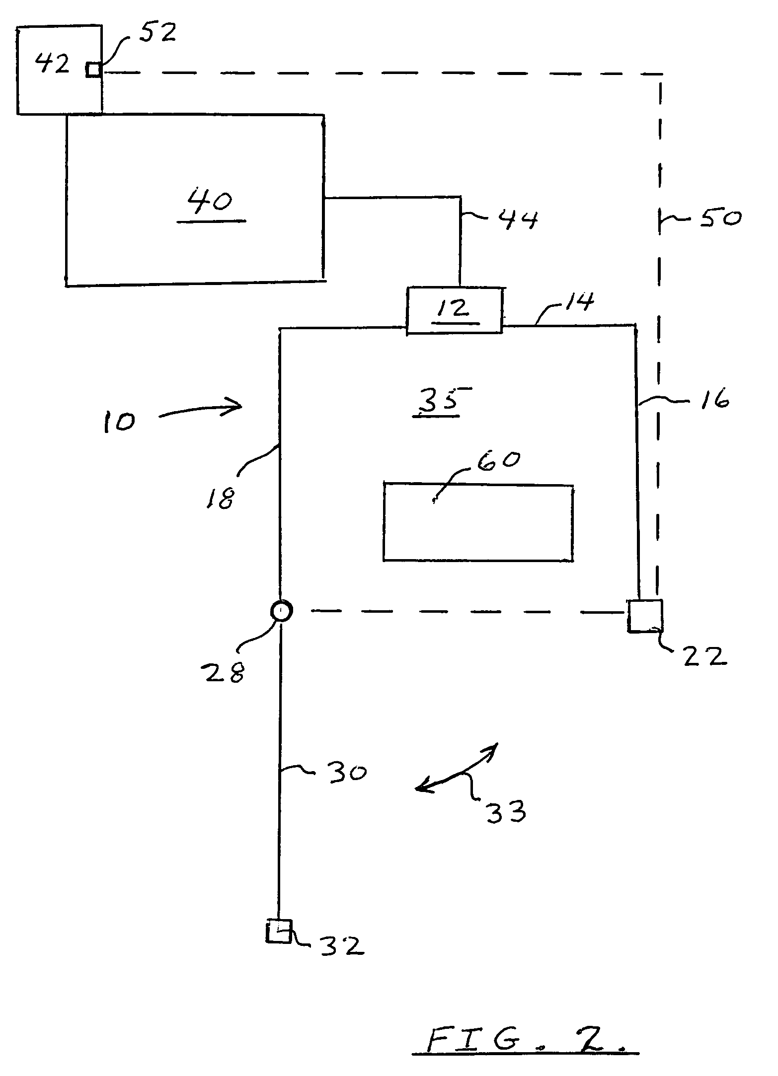
[0029]Referring to FIG. 2 which is an end view along line 2—2 of FIG. 1, the top bar 12 and left bracket 14 are again shown.

[0030]Left bracket 14 has a rear dep...


PUM


Abstract

A system and method for safely deploying a tire deflation device. Tire deflation units or stop sticks are released from a specially designed deployment unit positioned on the back of a police vehicle. A remote control feature allows a police officer to release a stop stick unit onto a roadway without exiting a police vehicle during a chase. A specially designed tire deflation or stop stick subcombination is also described. The overall design significantly improves safety and performance for law enforcement agencies involved in apprehending suspect fleeing vehicles. The invention also has utility for counter-terrorism activities when it is desired to disable a terrorist's vehicle at a certain location.

Description

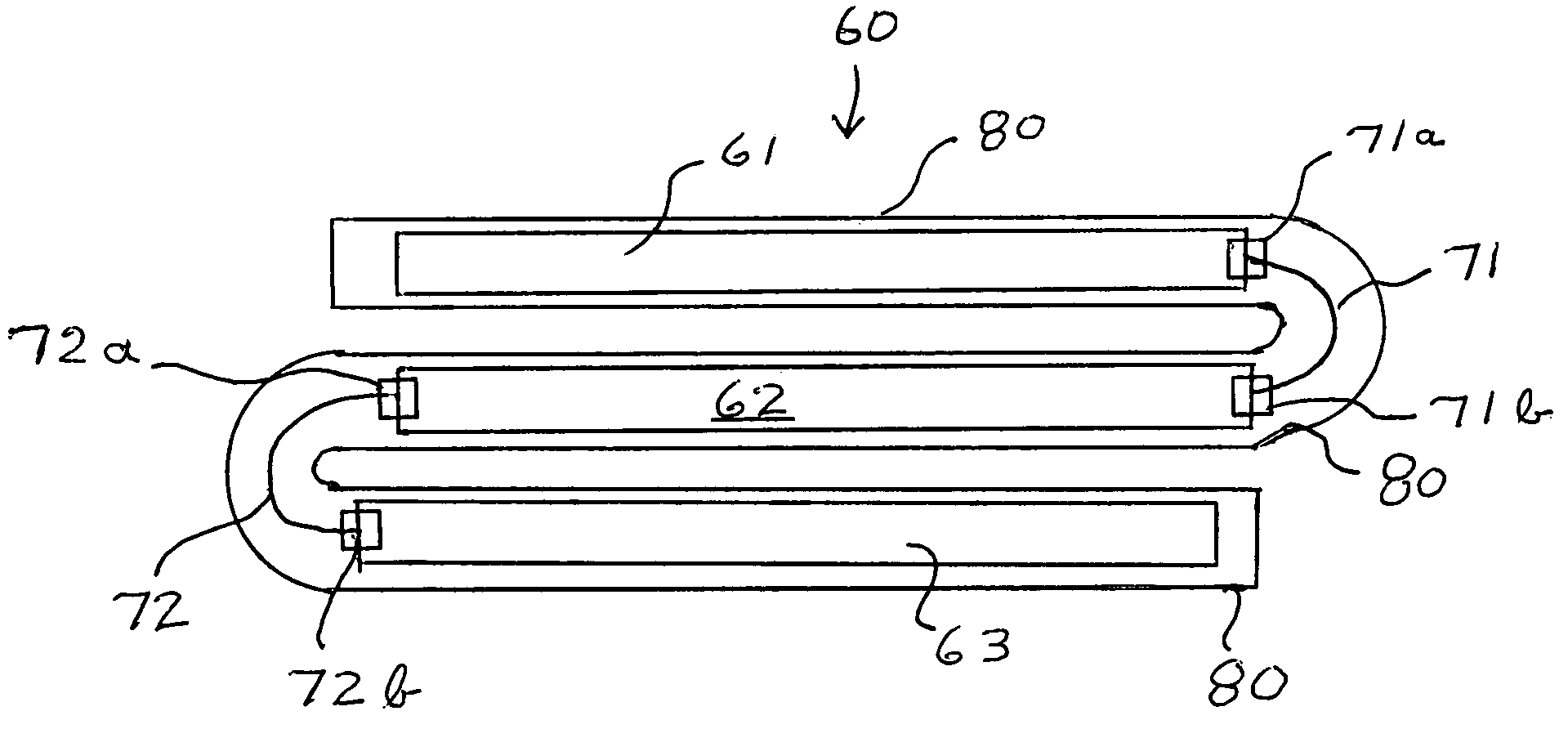
BACKGROUND AND OBJECTS OF THE INVENTION[0001]The following invention is generally related to the dispensing and roadway treatment arts and, in particular, to a system and method for deploying tire deflation devices upon a roadway.[0002]Vehicle tire deflation devices, as currently used by law enforcement personnel, have come to be known in the art as stop sticks.[0003]Such tire deflation devices have performed well in stopping vehicles fleeing law enforcement.[0004]One problem in the art has been that the tire deflation devices are typically manually placed upon a roadway by police personnel. Such personnel are thus placed in possible danger since they are required to leave the safety of a police vehicle.[0005]That is, the police personnel may be in danger of being struck by the fleeing vehicle, by the occupants of the fleeing vehicle or by other innocent bystander vehicles in the area.[0006]Accordingly, it is therefore an object of the present invention to set forth a novel device f...

Claims


Application Information

Patent Timeline
Patent Type & Authority Patents(United States)
IPC IPC(8): E01F13/12
CPCE01F13/12
Inventor KEITH, BRETTKEITH, LOWELLSNOW, DONALD
Owner KEITH BRETT
Learn More