Traction drive shaft seal

a technology of drive shaft and seal, which is applied in the direction of machines/engines, stators, liquid fuel engines, etc., can solve the problems of unsuitable materials to adequately seal the shaft pressure barrier interface, other types of seals such as ferromagnetic seals are not suitable for such extreme shaft speed and pressure combinations, and the single spring loaded carbon face seal is not acceptable. to achieve the effect of reducing the speed and reducing the sealing contact pressur

Inactive Publication Date: 2006-06-06
HAMILTON SUNDSTRAND CORP
View PDF13 Cites 8 Cited by
  • Summary
  • Abstract
  • Description
  • Claims
  • Application Information

AI Technical Summary

Benefits of technology

[0006]This invention is a traction drive seal assembly for sealing a shaft / pressure barrier interface for high shaft speed and high-pressure applications by reducing the speed at which the seal rotates relative to the shaft speed and by reducing the seal contact pressure.
[0008]The seal ring includes a plurality of seals biased outwardly against inner and outer wear inserts. The seals disposed within the seal ring include a calibrated leakage providing a predetermined pressure reduction at each seal. The reduction in speed of the seal ring and the reduction of pressure at each seal lowers the PV value and allows the use of known materials in applications that would otherwise exceed capabilities of known materials.

Problems solved by technology

However, there are extreme applications where shaft speeds may exceed 80,000 rpm and pressures may exceed 500 psi.
In such extreme applications, the PV values are such that known materials are unsuitable to adequately seal the shaft pressure barrier interface within acceptable leakage limits.
Other types of seals such as Ferromagnetic seals are not suitable for such extreme shaft speed and pressure combinations.
Further, a single spring loaded carbon face seal is not acceptable because the operating speeds of the shaft and pressure within the pressure chamber combine to require a PV value greater than 30 times allowable material combinations.

Method used


Image

  • Traction drive shaft seal
  • Traction drive shaft seal
  • Traction drive shaft seal

Examples


Embodiment Construction

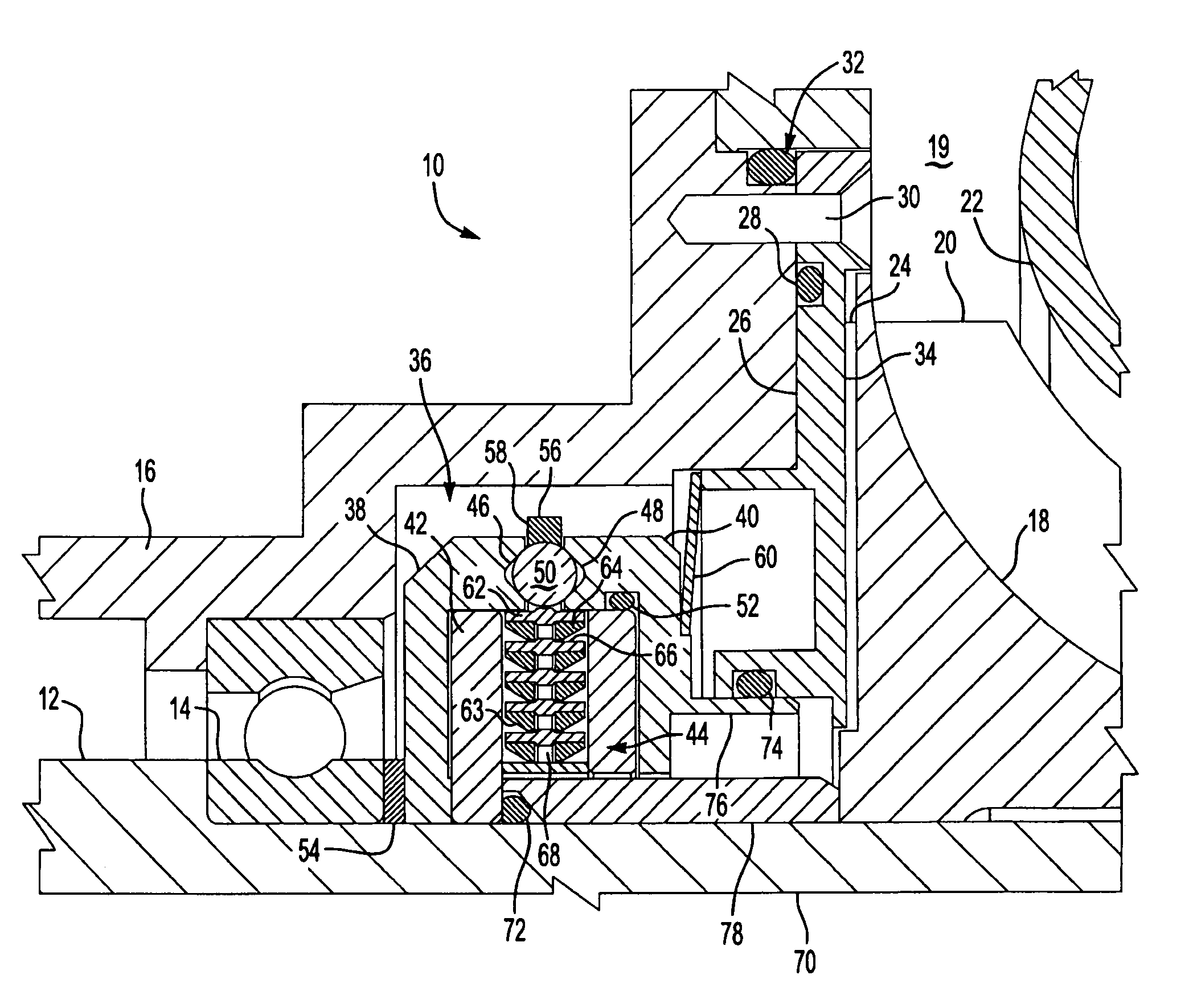
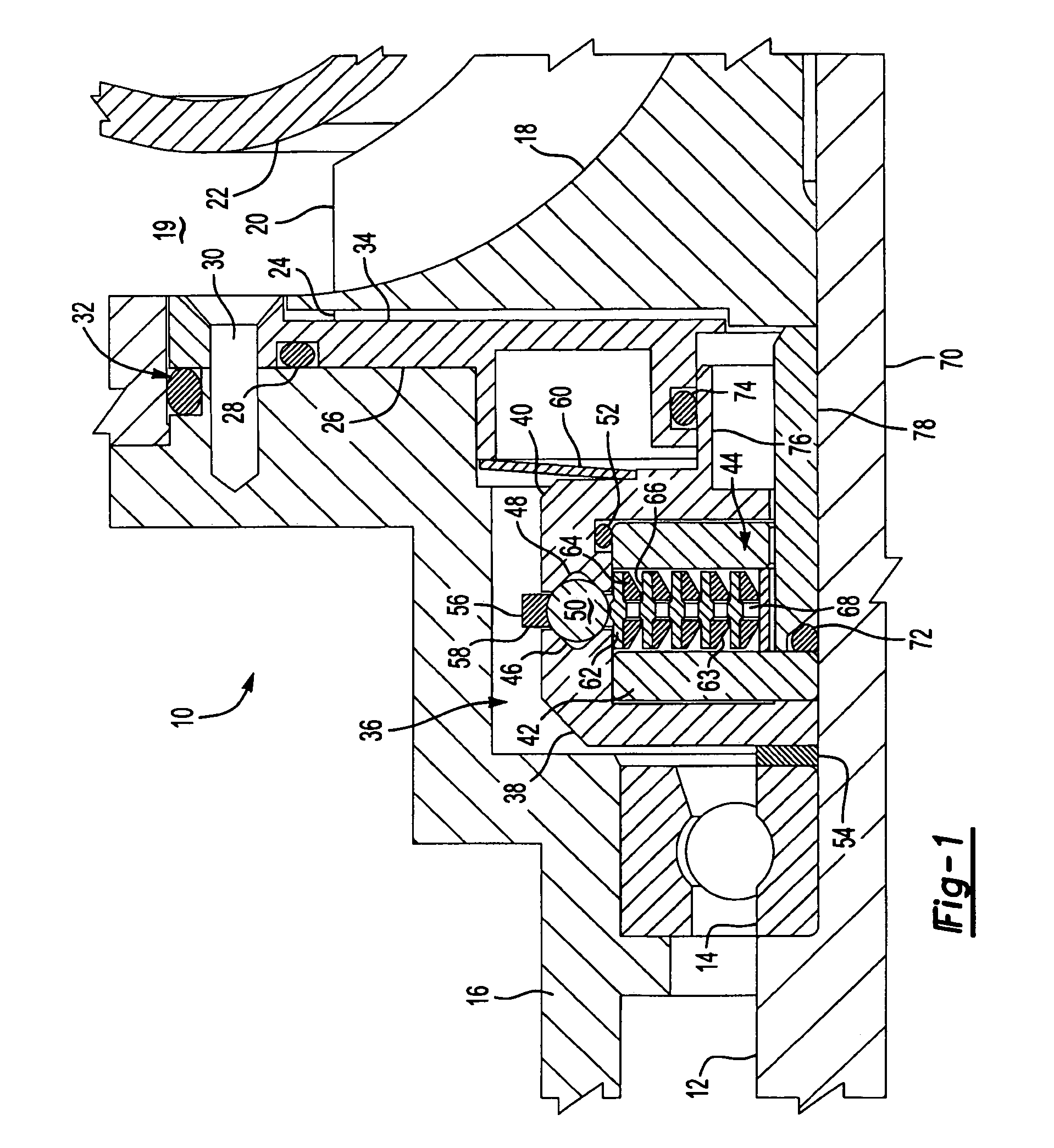
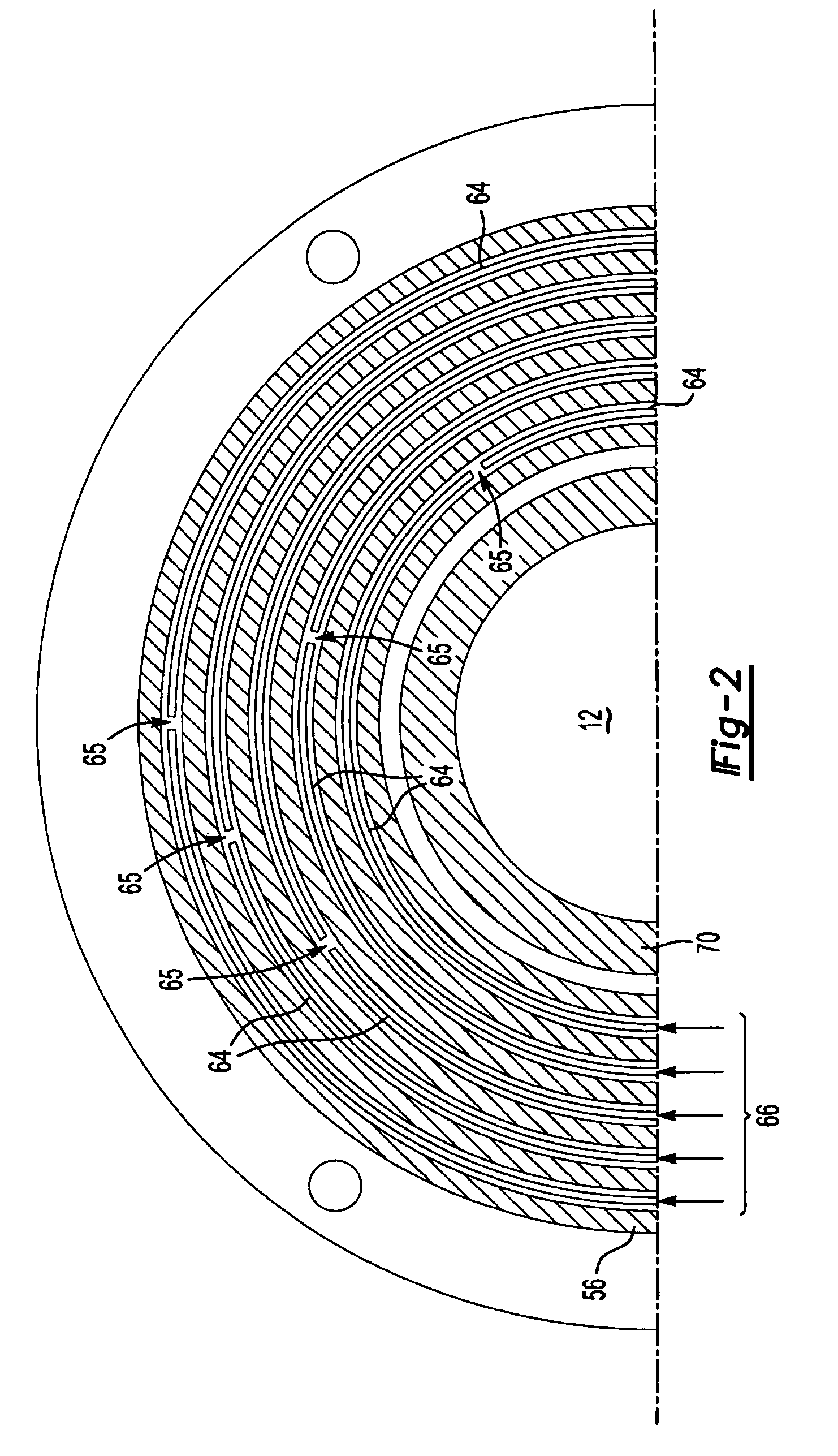
[0015]Referring to FIG. 1, a compressor assembly 10 includes a housing 16 supporting a shaft 12 for rotation of a rotor 18. The shaft 12 rotates at speeds that reach 80,000 rpm and the compressor assembly 10 contains gas at a pressure that can reach 500 psi. The shaft 12 penetrates a compressor chamber 19 requiring a seal at the pressure barrier shaft interface. The PV value using the possible shaft speeds and compressor chamber pressures exceeds the capabilities of known materials. The compressor assembly therefore utilizes a traction drive seal 36 that rotates multiple sealing elements 64 at a reduced pressure and speed relative to the shaft 12, lowering the PV value and allowing the use of known materials.

[0016]The shaft 12 is supported within the housing 16 by a bearing assembly 14. Gas within the compression chamber 19 is elevated to a high pressure by rotation of the rotor 18. The rotor 18 includes compression vanes 20, to compress the gas within the compression chamber 19. A ...


PUM


Abstract

A rotating shaft seal assembly for a shaft supported for rotation within a housing includes a traction drive rotating a seal ring about the shaft at a speed different from the shaft. The seal ring supports a plurality of seal elements rotated at the speed different from the shaft. The reduced speed of the sealing elements and reduced pressure at each seal reduces the PV level allowing the use of known sealing materials in applications otherwise not within applicable PV levels.

Description

BACKGROUND OF THE INVENTION[0001]This invention relates to a shaft seal assembly for sealing a rotating shaft penetrating a pressure barrier and specifically to a traction drive shaft seal assembly for shafts rotating at high-speeds penetrating high-pressure barriers.[0002]In many applications, a rotating shaft penetrates a pressure barrier to rotate a vane or rotor within a pressure chamber. A potential leak point is the interface between the shaft and the pressure barrier. Sealing the shaft / pressure barrier interface is typically accomplished by selecting suitable material for a mechanical contact seal between the rotating shaft and the pressure chamber housing. Selecting the proper material for each application is dependent on a known design parameter referred to as PV. The PV for a seal is determined by multiplying a seal contact pressure (P), by a surface velocity (V) of the shaft. The specific PV value for an application is then matched to known materials to construct a suitab...

Claims


Application Information

Patent Timeline
Patent Type & Authority Patents(United States)
IPC IPC(8): F01D11/00F01D25/18F04D29/12F16C33/76F16J15/00F16J15/34
CPCF01D11/003F01D25/183F16J15/3404F16C33/76F16J15/006F04D29/122
Inventor DEAN, W. CLARK
Owner HAMILTON SUNDSTRAND CORP
Why Eureka
Try Eureka