Electronic camera with device for eliminating static electric charges from optical element

a static electric charge and optical element technology, applied in the field of electronic cameras, can solve the problems of reducing the quality of the image obtained by the image pick-up device, reducing the quality of the image obtained by, and not being able to remove the dust completely by such methods, so as to prevent the deterioration of the quality of the object image

Inactive Publication Date: 2006-06-06
PENTAX RICOH IMAGING CO LTD
View PDF8 Cites 16 Cited by
  • Summary
  • Abstract
  • Description
  • Claims
  • Application Information

AI Technical Summary

Benefits of technology

[0010]It is therefore an object of the invention to provide an improved electrical camera that prevents deterioration of quality

Problems solved by technology

Such dust decreases the quality of the image formed on the image-pickup device.
Such dust also decreases the quality of the image obtained by the image-pickup device.
However, it is not easy to remove the dust

Method used


Image

  • Electronic camera with device for eliminating static electric charges from optical element
  • Electronic camera with device for eliminating static electric charges from optical element
  • Electronic camera with device for eliminating static electric charges from optical element

Examples


first embodiment

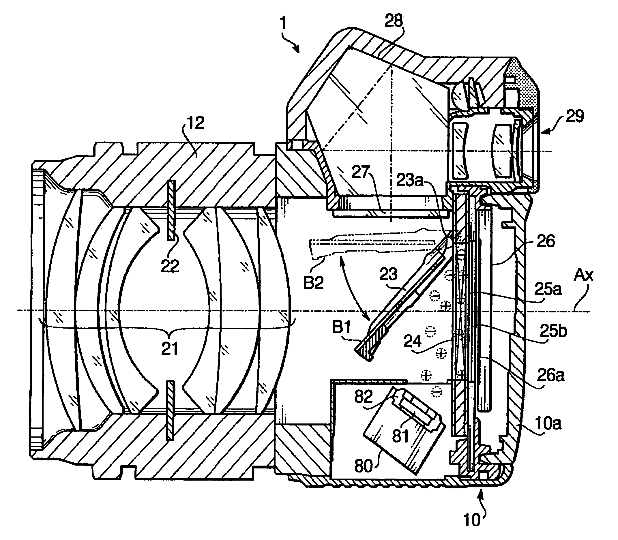
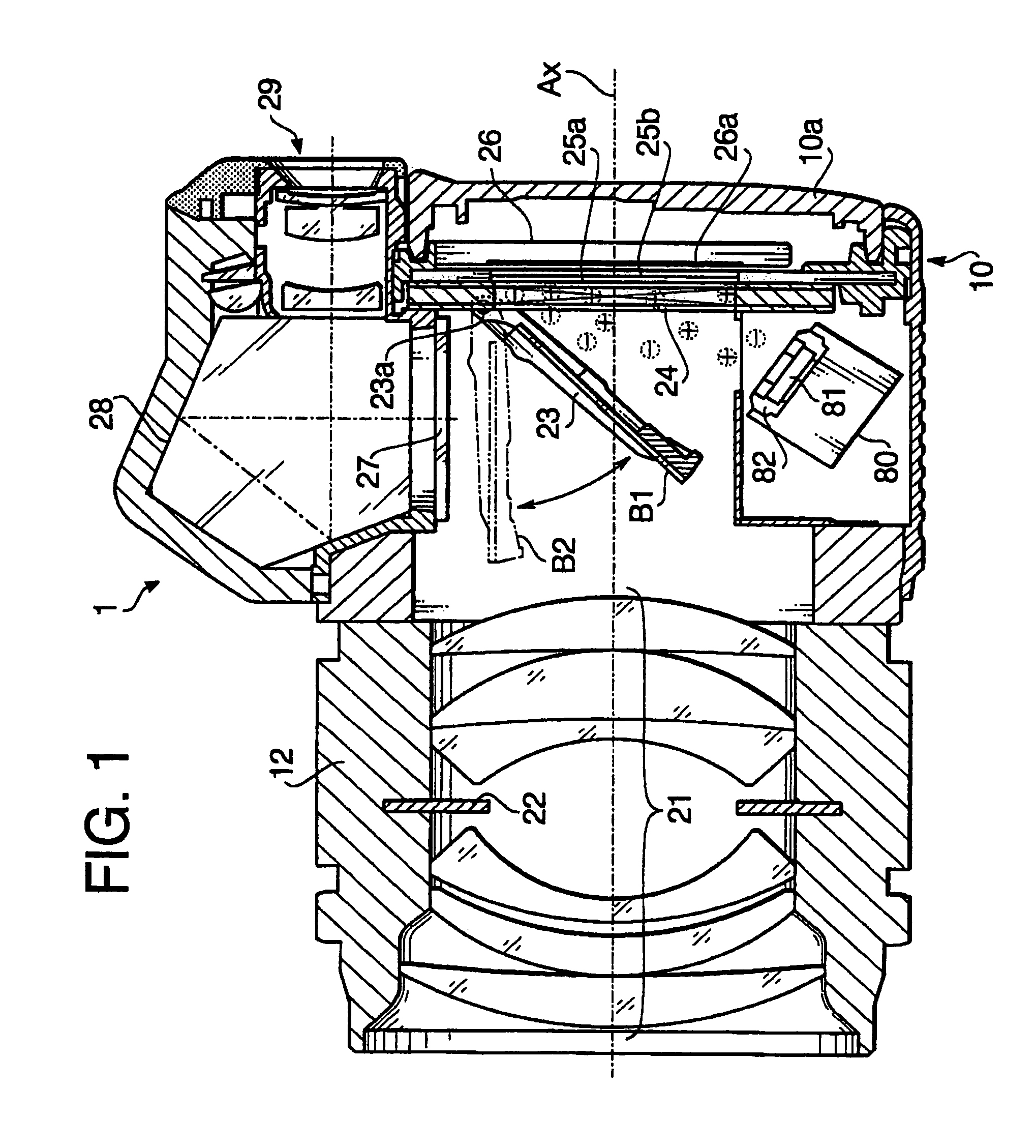
[0028]FIG. 1 schematically shows a cross-section of a digital camera 1 according to the present invention.

[0029]As shown in FIG. 1, the digital camera 1 has a camera body 10, and an interchangeable lens barrel 12 mounted on a front side of the camera body. The front side is the side which faces an object when a picture is taken.

[0030]The lens barrel 12 is provided with a photographing lens system 21, and an aperture member 22 which is disposed between the lenses of the photographing lens system 21.

[0031]A CCD image sensor 26, which serves as an image-pickup device, is disposed in front of a back cover 10a of the camera body 10. The CCD image sensor 26 is arranged in the camera body 10 such that its light receiving surface 26a faces the lens system 21, and an optical axis Ax of the lens system 21 crosses perpendicularly to the light receiving surface 26a, preferably, at its center.

[0032]A focal plane shutter 24 is provided in front of the CCD image sensor 26. The focal plane shutter ...

second embodiment

[0060]FIG. 4 schematically shows a cross-sectional view of an digital camera 2 according to the present invention.

[0061]The digital camera 2 has the same configuration as that of the digital camera 1 of the first embodiment except that the low-pass filter 25a and the infrared-absorbing filter 25b are disposed between the lens system 21 and the quick return mirror 23, and that the ion generator 80 is disposed such that the tip of the needle-shaped electrode 81 is directed toward the quick return mirror 23 so that the opening defined at the top of the electrode 82 faces the quick return mirror 23.

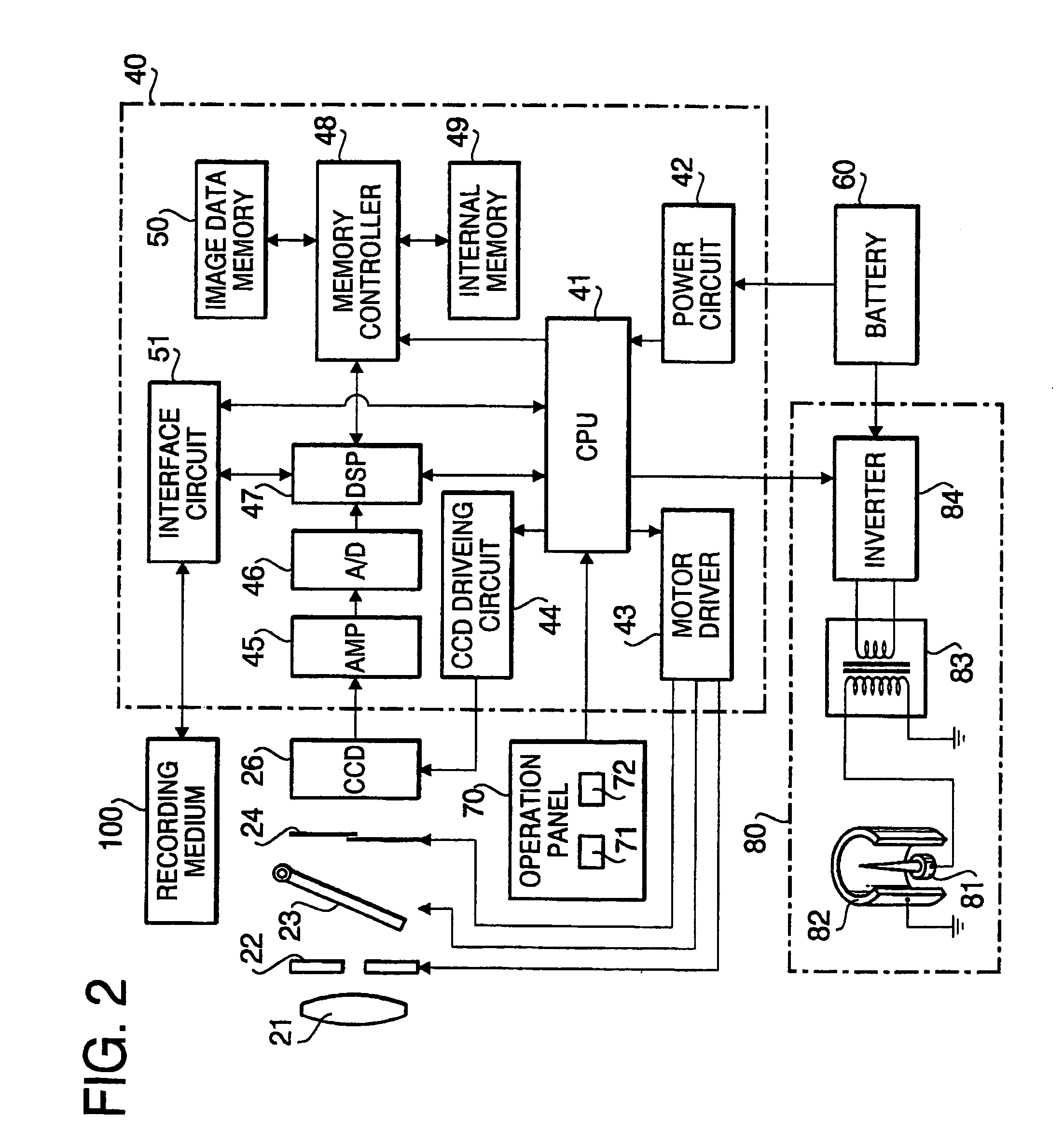
[0062]Similar to the first embodiment, the air around the needle-shaped electrode 81 is ionized and diffuses into the space accommodating the quick return mirror 23 when the neutralization button 72 is pushed by the camera user. Further, the focal plane shutter 24 fully opens its slit by moving the leading blind in the direction away from the trailing blind, and the quick return mirror 23 mov...


PUM


Abstract

An electronic camera is provided that prevents deterioration of quality of an object image obtained by an image-pickup device due to dust adhered on an optical element. The electronic camera includes an ion generator for taking off the electric charges from the optical element, such as a low-pass filter, arranged in front of the image-pickup device. The ion generator is provided in the camera body and ionizes the air inside the camera body. The ionized air diffuses toward the low-pass filter and binds with the charge on the low-pass filter. Thus, the electric charge of the low-pass filter is taken off and the low-pass filter does not attract dust which cause the quality decrease of the object's image obtained by the image-pickup device.

Description

BACKGROUND OF THE INVENTION[0001]The present invention relates to an electronic camera having an image-pickup device that converts an image of an object into electric signals.[0002]Recently, electronic still cameras and video cameras that electronically stores still images and animated images in memories have become popular. In these electronic cameras, a photographing lens system forms an image of the object on a light receiving surface of an image-pickup device, e.g., a CCD image sensor. The image-pickup device has a plurality of pixels arrayed in a lattice pattern, i.e., the pixels are arrayed at constant interval in both vertical and horizontal directions on the light receiving surface thereof. These pixels convert the optical image formed on the light receiving surface into electrical signals and the electrical signals obtained are further converted from analog to digital and then stored in a recording medium as image data.[0003]Such an electronic camera often includes a low-pa...

Claims


Application Information

Patent Timeline
IPC IPC(8): H04N5/225G03B19/02G03B17/02
CPCH04N5/2254H04N5/217H04N23/52H04N23/81H04N23/55H04N23/811
Inventor MOGAMIYA, MAKOTOFUSHIMI, MASAHIRO
Owner PENTAX RICOH IMAGING CO LTD
Why Eureka
Try Eureka