Scanning laser microscope with wavefront sensor

a laser microscope and wavefront sensor technology, applied in the field of scanning laser microscopes, can solve the problem of limited content of detected beams, and achieve the effect of enhanced resolution, enhanced resolution, and high resolution

Inactive Publication Date: 2006-06-06
3M INNOVATIVE PROPERTIES CO
View PDF36 Cites 67 Cited by
  • Summary
  • Abstract
  • Description
  • Claims
  • Application Information

AI Technical Summary

Benefits of technology

[0008]In another aspect, the present invention provides a method of high resolution imaging of an object, the method comprising: 1) scanning the object to produce pixel data representing light intensity at a plurality of pixel locations; 2) displaying an image of the object based upon the pixel data; 3) selecting a region of interest of the image; 4) scanning the region of interest; 5) producing, for each pixel location of the region of interest, wavefront shape data at that pixel location; 6) generating image data for each pixel location of the region of interest based upon the wavefront shape data from the pixel locations in the region of interest; and 7) displaying an image of the region of interest based upon the image data.
[0009]In another aspect, the present invention provides a method of producing an enhanced resolution scanned image of an object, the method comprising: 1) identifying a region of interest of the object having small scale features; 2) scanning pixel locations in the region of interest with a focused light beam; 3) collecting light from the scanned pixel locations; 4) sensing wavefront shape of the collected light from the scanned pixel locations; 5) determining from the wavefront shape of the collected light from each pixel location a high frequency spectrum corresponding to uncollected scattered light from small scale features of that scanned pixel location; and 5) providing an enhanced resolution image of the region of interest based on the high frequency spectra of the scanned pixel locations.
[0010]In another aspect, the present invention provides a method of producing an image of an object, the method comprising: 1) illuminating an object with an incident focused spot; 2) collecting light diffracted from low spatial frequency features of the object; 3) measuring intensity of the collected light; 4) deriving high spatial frequency features of the object based upon wavefront information of the collected light; and 5) displaying an enhanced resolution image of the object based upon the derived high spatial frequency features.

Problems solved by technology

The content of that detected beam is limited by the ability of the objective lens to collect light diffracted from the object.

Method used


Image

  • Scanning laser microscope with wavefront sensor
  • Scanning laser microscope with wavefront sensor
  • Scanning laser microscope with wavefront sensor

Examples


Embodiment Construction

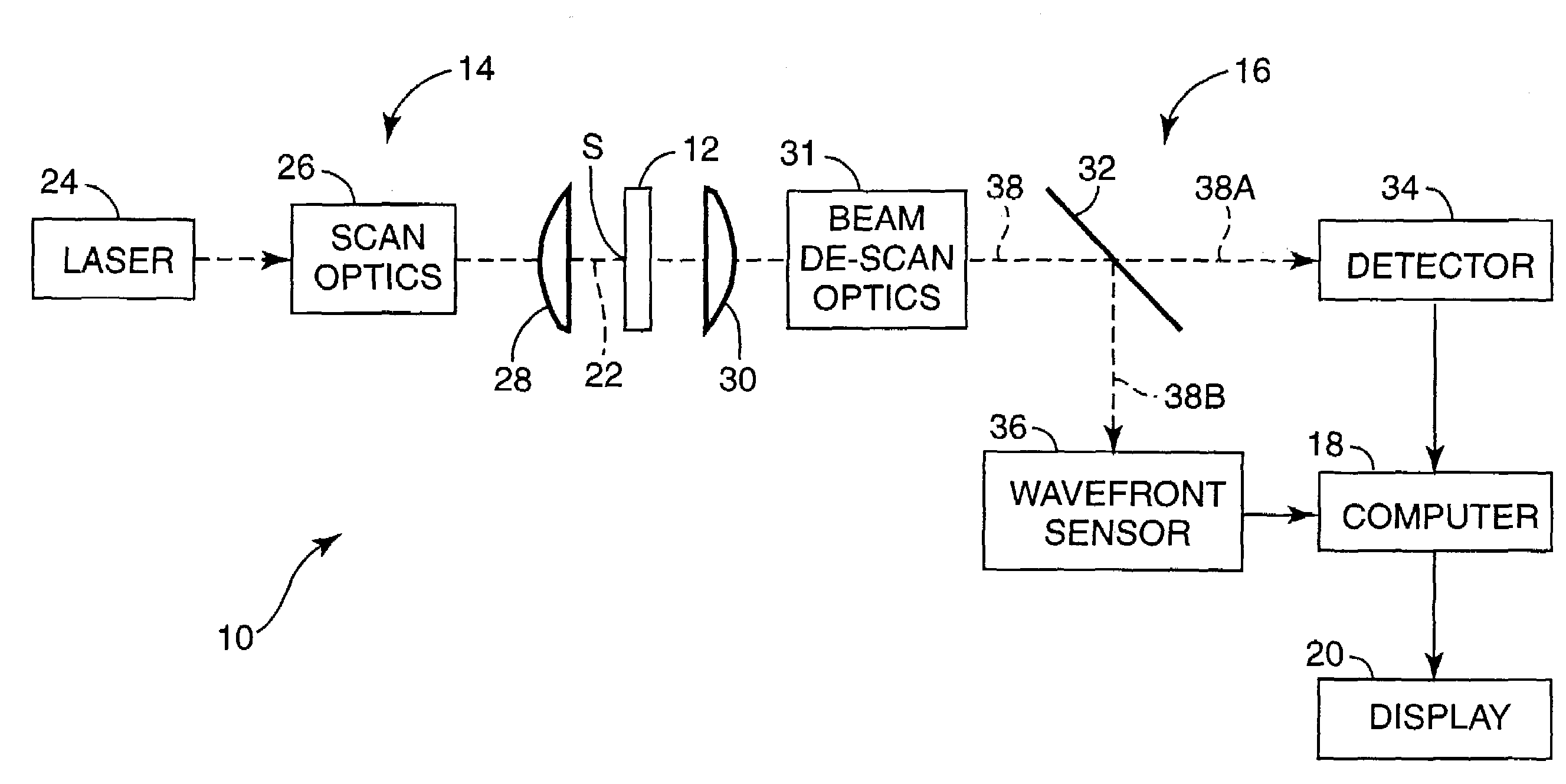
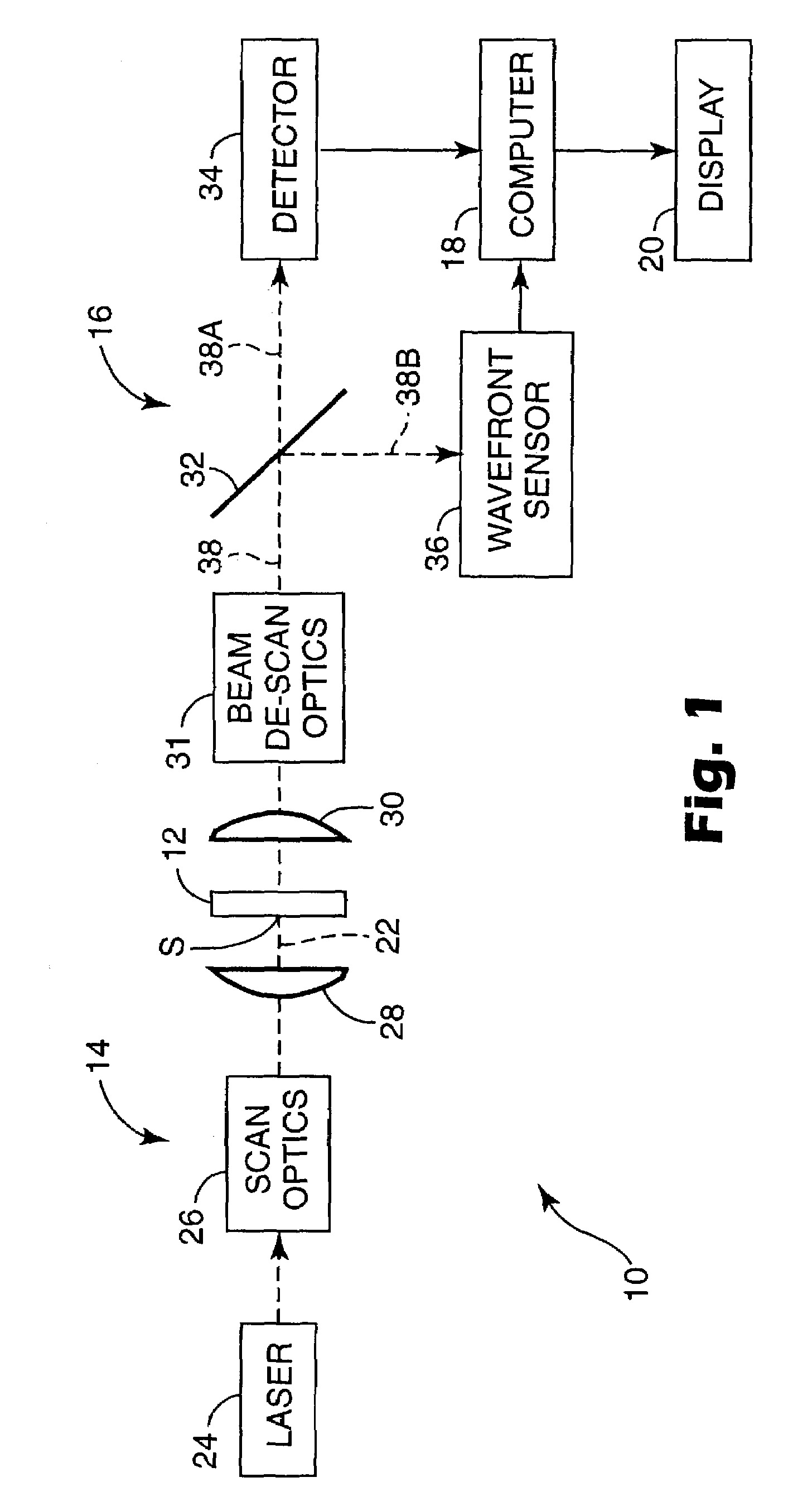
[0024]The present invention is an improved scanning laser microscope which includes a wavefront sensor for sensing phase variations of light from a region of interest in the object. The phase variations indicate a wavefront shape for the collected light at each scanned pixel location in the region of interest. From the wavefront shapes, a high frequency spectrum corresponding to uncollected scattered light can be derived. This scattered light is produced by small scale features of the scanned pixel location. An enhanced resolution image of the region of interest is then produced based upon the high frequency spectra of the scanned pixel locations.

[0025]The present invention is based upon the recognition that there is more information in the collected light in the detection arm of a scanning laser microscope than is typically used. By using a wavefront sensor in parallel with conventional detection, the portion of the spatial frequency spectrum above system cutoff can be determined f...


PUM


Abstract

An enhanced resolution scanned image of an object is produced by a scanning laser microscope which includes an illumination arm for scanning an object with a focused probe beam and a detection arm for receiving light from the object. The detection arm includes a detector which collects and detects light from the object to produce pixel data for a plurality of pixels. In addition, the detection arm includes a wavefront sensor for sensing phase variations of the light from the object to produce wavefront data for scanned pixel locations. From the wavefront shape of the collected light at each pixel location, a high frequency spectrum is determined which corresponds to uncollected scattered light from small scale features of that pixel location. An enhanced resolution image of a region of interest is produced based on the high frequency spectra of the scanned pixel locations.

Description

FIELD OF THE INVENTION[0001]The present invention relates to scanning laser microscopes. In particular, the present invention concerns an improved scanning laser microscope equipped with a wavefront sensor to collect wavefront data from scanned pixel locations. The wavefront data collected from the wavefront sensor can be used to produce an enhanced resolution image.BACKGROUND[0002]Known scanning laser microscopes include an illumination arm and a detection arm. The illumination arm generates a focused probe beam which is scanned across a sample or object. The reflected, scattered, or emitted light is collected and detected synchronously with the scanning to build up an image on a pixel-by-pixel basis. The detection arm of the microscope may include spectral filters (for fluorescence or photoluminance imaging), a spatial filter (for confocal imaging) and / or a polarization analyzer (for polarization imaging).[0003]The detection arm of the scanning laser microscope includes an objecti...

Claims


Application Information

Patent Timeline
Patent Type & Authority Patents(United States)
IPC IPC(8): G02B21/00
CPCG02B21/002G02B21/00G02B21/06G02B21/14
Inventor ATKINSON, MATTHEW R. C.
Owner 3M INNOVATIVE PROPERTIES CO
Why Eureka
Try Eureka