
Method, device and system for delay equalizing in high rate data streams

a delay equalization and data stream technology, applied in data switching networks, frequency-division multiplexes, instruments, etc., can solve the problems of synchronizing the transmission of fragments, affecting the quality of data, so as to achieve the effect of minimizing or equalizing delay differences

Inactive Publication Date: 2006-06-06
ECE TELECOM LTD
View PDF12 Cites 8 Cited by
  • Summary
  • Abstract
  • Description
  • Claims
  • Application Information

AI Technical Summary

Benefits of technology

[0026]In general, the proposed method provides gradual minimization of differential delay in a virtual data stream at one or more intermediate points between a source point and a destination point of said stream.
[0057]Finally, a set of equipment for gradual minimization of a differential delay in a virtual data stream, comprising one or more above-defined device(s) for minimizing a differential delay, is also considered an aspect of the invention. The set may additionally include a suitable source network element, and / or a suitable destination network element. The set may specifically be designed for handling one or more SDH / SONET concatenated virtual stream(s).

Problems solved by technology

Therefore, a problem arises how to synchronize the transmission of fragments of the disassembled concatenated stream via different paths that usually have different delays.
Moreover, the delays may change.
Indeed, when the fragments arrive to the point of re-assembling, the delay difference there-between may become so great and / or disordered that it will prevent the proper restoration of the initial stream.
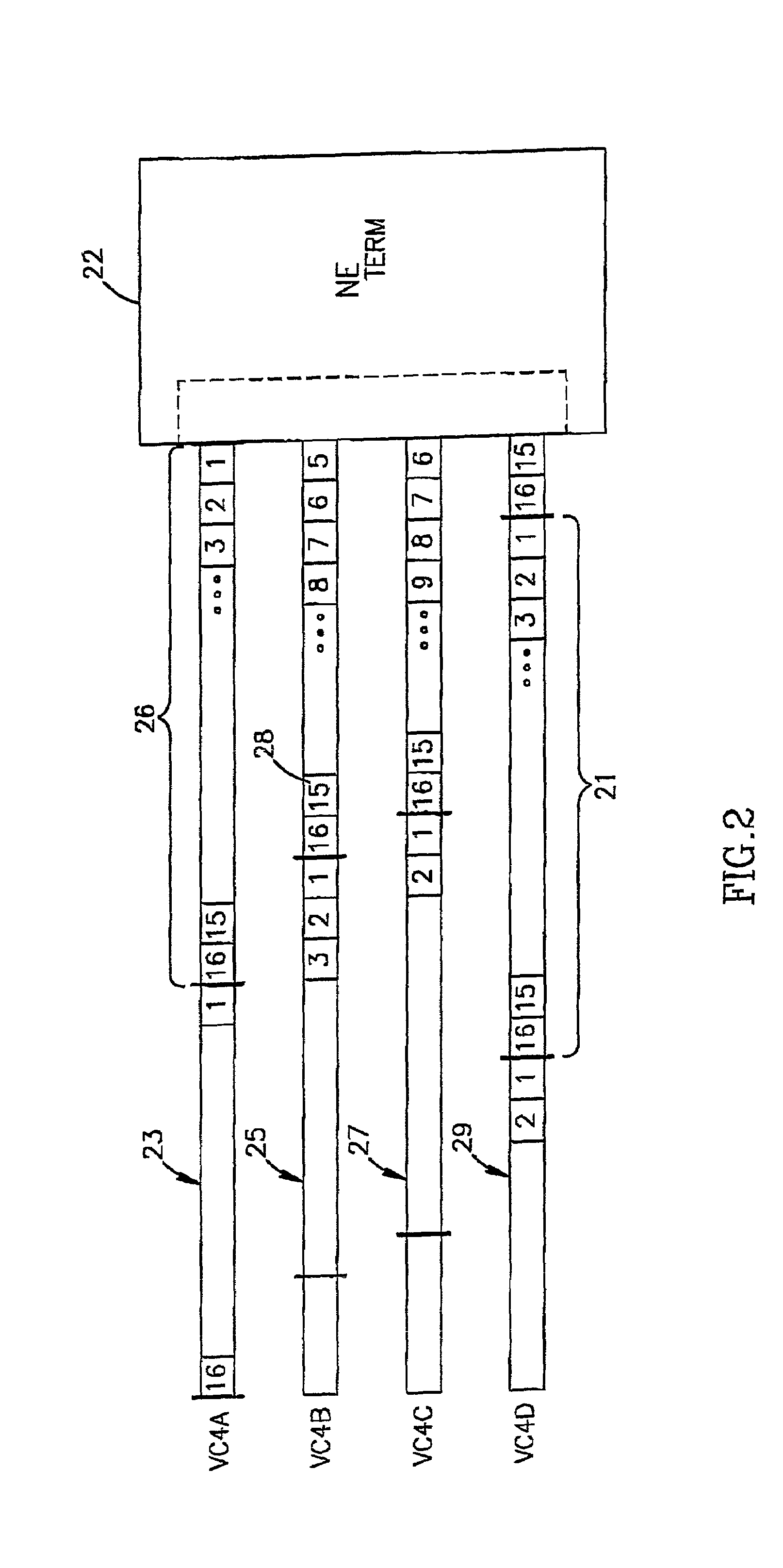
However, if the delay difference between the VC4 streams, following along the parallel paths approaches and even exceeds a ½ cycle period (being ½ the length of the multiframe), the delay difference between the VC4 streams will become indistinguishable and the correct order will be lost.
In other words, with a given equipment at the destination point (the point of re-assembling fragments of the concatenated stream), the problem may become unsolvable at a particular moment when one or more of the parallel channels change their delay.

Method used


Image

  • Method, device and system for delay equalizing in high rate data streams
  • Method, device and system for delay equalizing in high rate data streams
  • Method, device and system for delay equalizing in high rate data streams

Examples


Embodiment Construction

.

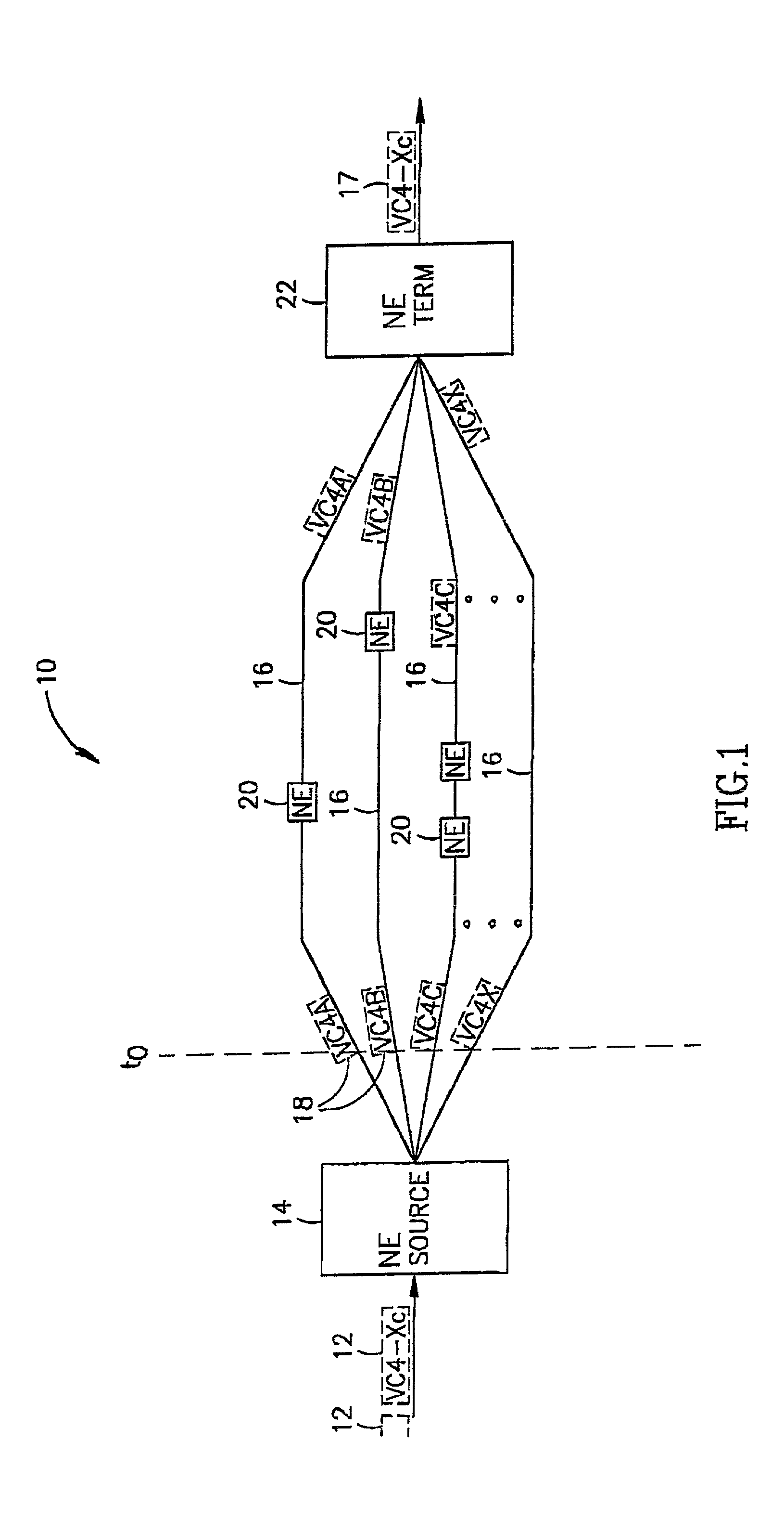
[0065]FIG. 1 illustrates a prior art arrangement, where a contiguous concatenated data stream (VC4-Xc in this particular embodiment) is transmitted via a telecommunication network 10 in the form of virtual concatenated data stream VC4-X, for example through a number of optical fibers typically disposed in one cable. It should be appreciated that another concatenated data stream (belonging to SONET and / or SDH) could be illustrated in this drawing. On the way, the cable may be split, reunite again, but at the destination point the fibers must meet together. The initial concatenated signal, which is schematically depicted as a sequence of long dotted contours 12, is transformed into a virtual form by a so-called source network element 14, so that “X” fragment signals are simultaneously launched onto “x” respective individual paths 16 and then transmitted there-along. The fragment signals (VC4A, VC4B, VC4C . . . VC4X) produced from the concatenated signal 12, are schematically illustra...


PUM


Abstract

A method, a device and a system for delay equalizing of fragment data streams transmitted via N individual paths and forming a virtual data stream, wherein the virtual data stream and each of said fragment data streams consisting of data frames; the method including gradual minimization of differential delay of the fragment data streams at one or more intermediate points between a source point and a destination point of the virtual data stream. The gradual minimization of the differential delay can be provided by devices (30, 32) respectively fitted at the intermediate points; each of the devices comprises a control unit (36) and N memory buffer blocks (34), each associated with a respective individual path.

Description

FIELD OF THE INVENTION[0001]The present invention relates to a method for supporting a high rate data stream which is divided into a number of lower rate fragments to be transmitted individually via parallel paths according to a so-called Inverse Multiplexing technology. More particularly, the invention concerns minimizing delay differences between such fragments, and specifically deals with delay equalizing for a virtual concatenated data stream before converting it into a contiguous concatenated stream in telecommunication systems of SONET / SDH.BACKGROUND OF THE INVENTION[0002]The Synchronous Digital Hierarchy (SDH) and its North-American equivalent, the Synchronous Optical Network (SONET), are the globally accepted, closely related and compatible standards for data transmission in the public wide area network (WAN) domain. Recently, SDH / SONET has also been adopted by the ATM Forum as a recommended physical-layer transmission technology for ATM (Asynchronous Transfer Mode) network ...

Claims


Application Information

Patent Timeline
IPC IPC(8): H04L12/56H04J3/06H04Q11/04
CPCH04J3/062H04J2203/0094
Inventor YEHUDA, EITANSHAKED, EYALHALEVI, ILAN
Owner ECE TELECOM LTD
Learn More