Hearing aid with a radio frequency receiver

a radio frequency receiver and hearing aid technology, applied in the field of hearing aids, can solve the problems of difficult and often even impossible to incorporate a number of crystals corresponding to the desired receiving frequency, difficult and often even impossible to change a crystal, etc., and achieve the effect of facilitating channel selection

Inactive Publication Date: 2006-06-06
OTICON
View PDF9 Cites 5 Cited by
  • Summary
  • Abstract
  • Description
  • Claims
  • Application Information

AI Technical Summary

Problems solved by technology

The very limited space available in such devices makes it difficult and often even impossible to incorporate a number of crystals corresponding to the desired receiving frequencies.
The change of a crystal is rather difficult due to the small size of these elements and the process is rather time consuming.
When however a larger number of frequencies is desired the same problem as described above exists.

Method used


Image

  • Hearing aid with a radio frequency receiver
  • Hearing aid with a radio frequency receiver
  • Hearing aid with a radio frequency receiver

Examples


Embodiment Construction

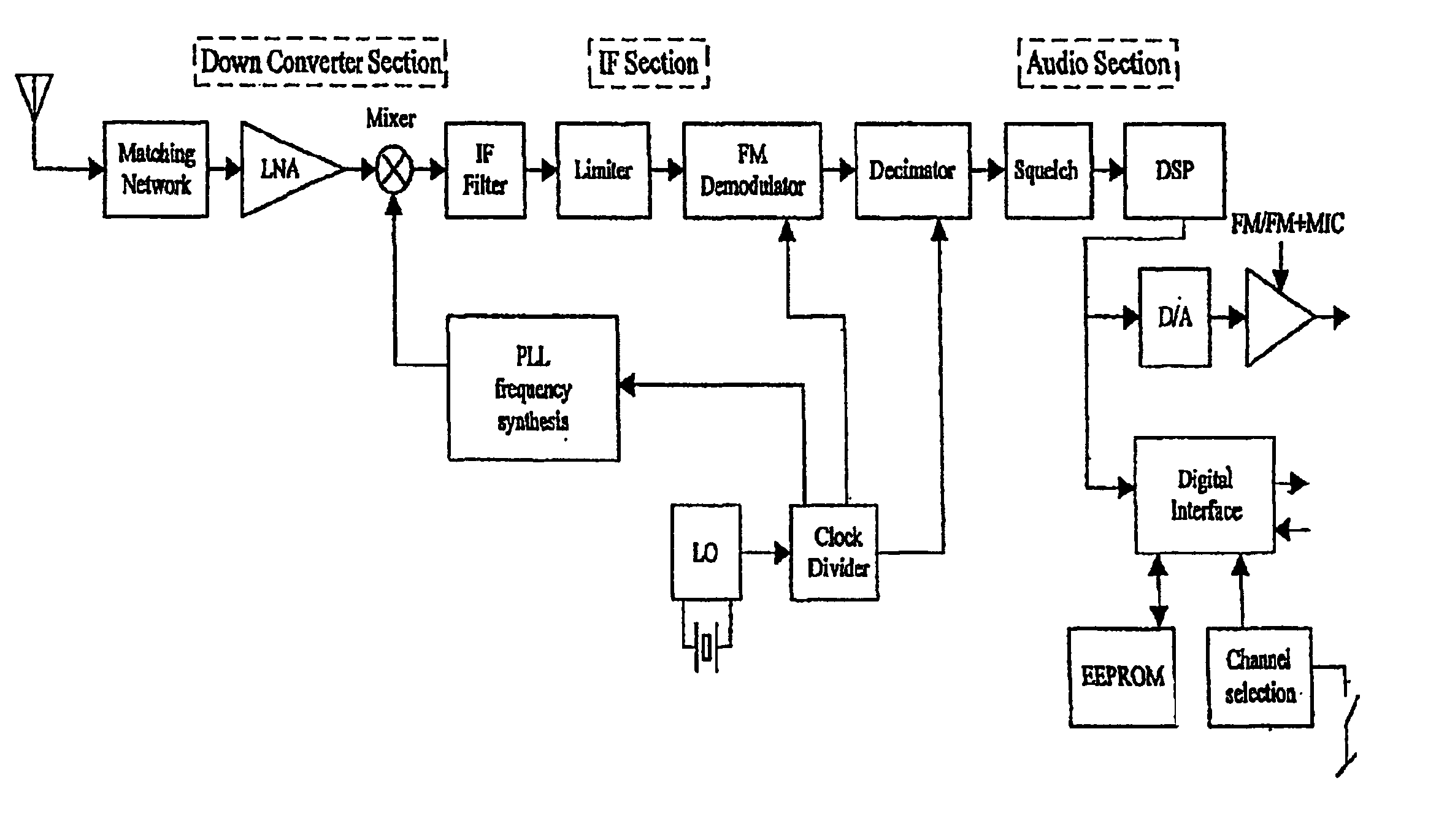
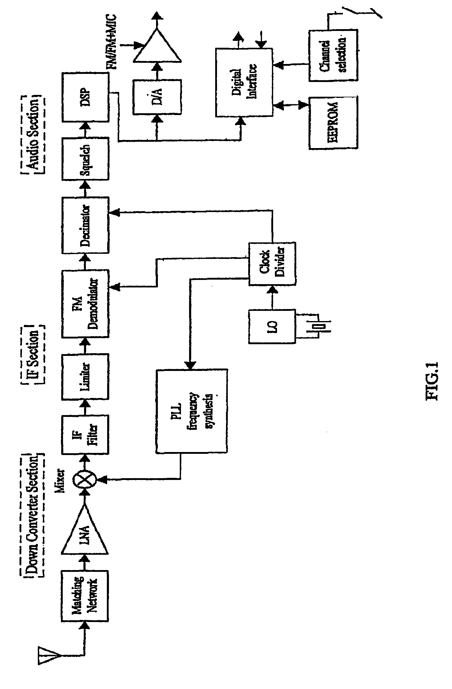
[0016]The analog RF signal is picked up by an antenna, which is connected to the on-chip LNA through an external matching network. The matching network is needed to make the RF receiver flexible towards different types of antennas, and to keep the current consumption down in the LNA.

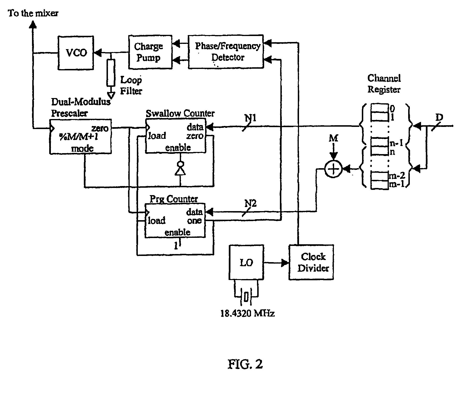
[0017]The LNA (Low Noise Amplifier) is used to amplify the weak signal, which is picked up on the antenna Low noise is essential due to the low signal level at the input. The LNA wires the signal on to the mixer, which as the second input gets the desired channel frequency from the frequency synthesizer. The frequency synthesis system is described further in connection with FIG. 2.

[0018]The mixer mixes the signal down to an intermediate frequency (IF) of 35 KHz, which is the lowest intermediate frequency acceptable with the given audio bandwidth and frequency deviation. To support the wide range of synthesisable frequencies, the mixer and LNA needs wide operating conditions with regards to input frequenc...


PUM


Abstract

A hearing aid including a radio frequency receiver, where the receiver includes a single oscillator providing a single crystal oscillator frequency and where means are provided for generating a further number of receiving frequencies by transforming the oscillator frequency to the desired receiving frequencies, where further scanning means are provided for upon activation provide a scanning of the possible frequency area and select a detected frequency superceding a predetermined detector level.

Description

AREA OF THE INVENTION[0001]The invention relates to the area of hearing aids comprising a radio frequency receiver. The receiver may be a built in receiver or an external receiver attached to the hearing aid by suitable means.BACKGROUND OF THE INVENTION[0002]One example of a hearing aid with a RF receiver is disclosed in CH 641619. The hearing aid with a RF receiver shown in this prior art document and other similar products available on the market today all comprise a single frequency receiving possibility. From U.S. Pat. No. 5,802,183 a further hearing aid is known which comprises the possibility of shifting between two frequencies, due to the presence of two crystals for determining the receiving frequency. In all of these previously known devices the frequency may be changed by changing the crystal element present for determining the receiving frequency. The very limited space available in such devices makes it difficult and often even impossible to incorporate a number of cryst...

Claims


Application Information

Patent Timeline
Patent Type & Authority Patents(United States)
IPC IPC(8): H04R25/00
CPCH04R25/554
Inventor BALLISAGER, LARSKLEMMENSEN, BJARNE
Owner OTICON
Why Eureka
Try Eureka