Eureka AIR delivers breakthrough ideas for toughest innovation challenges, trusted by R&D personnel around the world.

Front-end device for digital radio frequency receiver, receiver and front-end receiving method

A receiver front-end and digital radio frequency technology, which is applied in the field of microwave photonics, can solve the problems of limited optical transmission distance of radio frequency signals, high requirements for experimental conditions, and system instability, and achieve simplified system complexity, low environmental requirements, and improved reception performance effect

Inactive Publication Date: 2011-10-05
BEIJING UNIV OF POSTS & TELECOMM
View PDF2 Cites 10 Cited by
  • Summary
  • Abstract
  • Description
  • Claims
  • Application Information

AI Technical Summary

Problems solved by technology

However, the most important disadvantages of this solution are:
[0005] 1. Affected by the phase noise of the laser source, the system is unstable and requires high experimental conditions, so it can only stay in the laboratory stage;
[0006] 2. The system is complex and expensive;
[0007] 3. The optical transmission distance of radio frequency signals is limited

Method used


Image

  • Front-end device for digital radio frequency receiver, receiver and front-end receiving method
  • Front-end device for digital radio frequency receiver, receiver and front-end receiving method
  • Front-end device for digital radio frequency receiver, receiver and front-end receiving method

Examples


Embodiment Construction

[0054] The specific implementation manners of the present invention will be further described in detail below in conjunction with the accompanying drawings and embodiments. The following examples are used to illustrate the present invention, but are not intended to limit the scope of the present invention.

[0055] Such as figure 2 Shown, the broadband of the present invention, the digital radio frequency receiver front-end device structure of large dynamic range comprises: light source, four polarization controllers (the first polarization controller, the second polarization controller, the 3rd polarization controller and the 4th polarization controller controller), electro-optical polarization modulator, fiber beam splitter, two polarization beam splitters (the first polarization beam splitter and the second polarization beam splitter), two balanced detectors (the first balanced detector and the second Two balanced detectors) and a signal processing module. in,

[0056] Th...


PUM


Abstract

The invention discloses a front-end device for a digital radio frequency receiver, belonging to the technical field of microwave photons. The front-end device comprises a light source, an electrooptic polarization demodulator, a first polarization controller, a second polarization controller, a fiber beam splitter, a third polarization controller, a fourth polarization controller, a first polarization beam splitter, a second polarization beam splitter, a first balanced detector, a second balanced detector, a first analog / digital converter, a second analog / digital converter and a DSP (Digital Signal Processor). The invention also discloses a digital radio frequency receiver using the front-end device and a front-end receiving method thereof. The large dynamic front-end device for the digital radio frequency receiver, which has low cost and low environmental requirements, is realized.

Description

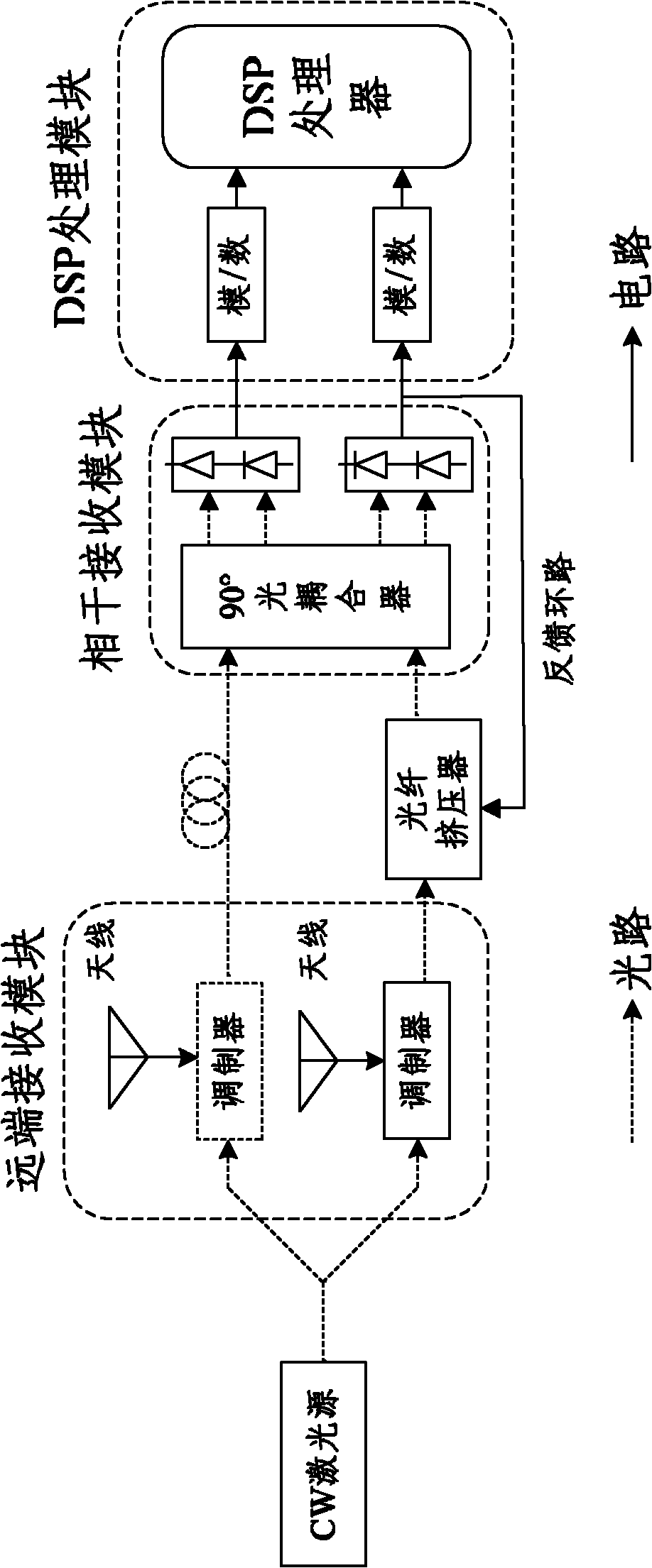
technical field [0001] The invention relates to the field of microwave photon technology, in particular to a digital radio frequency receiver front-end device, a receiver and a front-end receiving method. Background technique [0002] The radio frequency front end of the receiver is located at the forefront of the receiver, and its structure and performance directly affect the entire receiver. At present, the traditional RF front-end includes many electronic devices, such as electric amplifiers, mixers, filters, and phase shifters. These electronic devices will generate serious nonlinear distortion and introduce noise, making it increasingly difficult to improve the performance of the RF front-end. The rise of microwave photonics has opened up a new way of thinking for the receiver RF front end. Microwave photonics technology can realize a digital radio frequency receiver with wideband and large dynamic range. [0003] figure 1 It is the RF optical front end based on the ...

Claims


Application Information

Patent Timeline
IPC IPC(8): H04B10/148H04B10/12H04B10/2575
Inventor 徐坤吕强戴一堂李岩洪小斌伍剑林金桐
Owner BEIJING UNIV OF POSTS & TELECOMM
Why Eureka
Eureka Blog
Learn More