Vehicular motion control apparatus and vehicular motion control method

a technology of vehicle motion control and control apparatus, which is applied in the direction of vessel construction, steering initiation, instruments, etc., can solve the problems of inability to precisely detect steering angle, inability to calibrate the neutral point of the steering angle sensor, and inability to control the motion of the vehicle suitably

Active Publication Date: 2006-06-06
TOYOTA JIDOSHA KK
View PDF18 Cites 46 Cited by
  • Summary
  • Abstract
  • Description
  • Claims
  • Application Information

AI Technical Summary

Benefits of technology

[0016]According to the aforementioned second aspect, a plurality of target vehicle state quantities are calculated on the basis of a plurality of steering angles estimated from a steering angle detected by the steering angle sensor, a reference rotational position of the steering angle sensor is determined on the basis of a steering angle corresponding to the minimum one of the differences between an actual vehicle state quantity and the target vehicle state quantities, and a steering angle for controlling motion of the vehicle is then calculated on the basis of the reference rotational position thus determined and the steering angle detected by the steering angle sensor. Therefore, a steering angle can be precisely detected by means of the steering angle sensor and motion of the vehicle can be suitably controlled without requiring any means for storing a steering angle even when an ignition switch is off and even unless the vehicle is traveling straight on at a constant speed.

Problems solved by technology

Also, if a driver operates the steering wheel to cause a change in steering angle before the ignition switch is turned on and aft the ignition switch has been turned off, it is impossible to precisely detect a steering angle.
This causes a problem in that motion of the vehicle cannot be controlled suitably.
In the case of this method, however, there is a problem in that the neutral point of the steering angle sensor cannot be calibrated unless it is detected that the vehicle is traveling straight on at a constant speed.

Method used


Image

  • Vehicular motion control apparatus and vehicular motion control method
  • Vehicular motion control apparatus and vehicular motion control method
  • Vehicular motion control apparatus and vehicular motion control method

Examples


Embodiment Construction

[0025]Some preferred embodiments (hereinafter referred to simply as embodiments) of the invention will be described in detail with reference to the accompanying drawings.

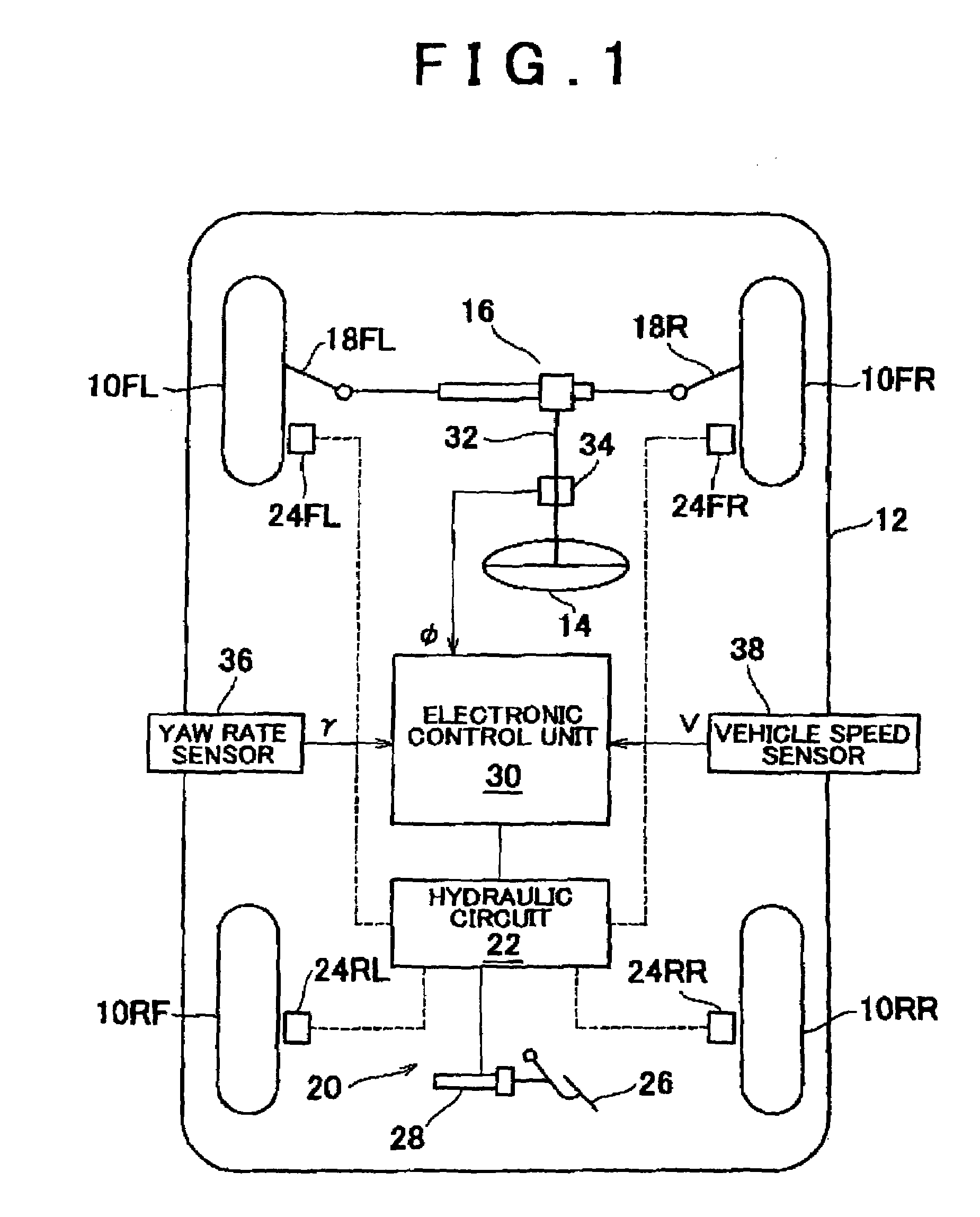
[0026]FIG. 1 is a schematic block diagram showing a vehicular motion control apparatus in accordance with the first preferred embodiment of the invention.

[0027]Referring to FIG. 1, reference symbols 10FL and 10FR denote front-left and front-right wheels of a vehicle 12 respectively, while reference symbols 10RL and 10RR denote rear-left and rear-right wheels of the vehicle 12 respectively. The rear-left and rear-right wheels 10RL and 10RR are driving wheels of the vehicle 12. The front-left and front-right wheels 10FL and 10FR, which are driven wheels and wheels to be steered, are steered by a rack-and-pinion power steering unit 16 via tie rods 18L and 18R respectively. The rack-and-pinion power steering unit 16 is driven in response to the turning of a steering wheel 14 by a driver.

[0028]A hydraulic circuit 22 of a...


PUM


Abstract

A vehicular motion control apparatus uses a steering angle detected by a steering angle sensor capable of detecting an absolute rotational angle. This control apparatus has a yaw rate sensor. If a reference rotational position of the steering angle sensor has not been determined, the control apparatus calculates a plurality of target yaw rates on the basis of a plurality of steering angles estimated from a steering angle detected by the steering angle sensor, and controls motion of a vehicle on the basis of the minimum one of differences between the target yaw rates and an actual yaw rate. The control apparatus determines a reference rotational position of the steering angle sensor on the basis of a steering angle corresponding to the minimum one of the differences, and then calculates a steering angle for motion control on the basis of the detected steering angle and the determined reference rotational position.

Description

INCORPORATION BY REFERENCE[0001]The disclosure of Japanese Patent Application No. 2002-313696 filed on Oct. 29, 2002, including the specification, drawings, and abstract is incorporated herein by reference in its entirety.BACKGROUND OF THE INVENTION[0002]1. Field of the Invention[0003]The invention relates to a vehicular motion control apparatus and a vehicular motion control mode. More specifically, the invention relates to a vehicular motion control apparatus and a vehicular motion control method for controlling motion of a vehicle using a steering angle detected by a steering angle sensor.[0004]2. Description of the Related Art[0005]According to a vehicular motion control apparatus for an automobile or the like as a known example, a target behavior of a vehicle is calculated at least on the basis of a detected value of a steeling angle relative to a neutral position of a steering wheel, and motion of the vehicle is controlled in accordance with a difference between a target value...

Claims


Application Information

Patent Timeline
Patent Type & Authority Patents(United States)
IPC IPC(8): G06F7/00G06F17/00G06F19/00G01B21/22B60T8/1755B60W30/00B62D6/00B62D15/02B62D101/00B62D111/00B62D113/00B62D137/00
CPCB62D15/02
Inventor INAGAKI, SHOJI
Owner TOYOTA JIDOSHA KK
Why Eureka
Try Eureka