Communication connection bypass method capable of minimizing traffic loss when failure occurs

a communication connection and bypass method technology, applied in the field of communication connection bypass method, can solve the problems of communication connection bypass system described above, and large amount of link resources consumed per backup communication connection, so as to achieve the effect of less link resources

Active Publication Date: 2006-06-06
NEC CORP
View PDF14 Cites 30 Cited by
  • Summary
  • Abstract
  • Description
  • Claims
  • Application Information

AI Technical Summary

Benefits of technology

[0013]Accordingly, a first object of the present invention is to provide a communication connection bypass method that allows a backup communication connection to consume less link resources.
[0014]A second object of the present invention is to provide a communication connection bypass method that can achieve the first object described above even when a backup communication connection is established for each of a plurality main communication connections for load balancing of traffic between two given nodes in a network.
[0016]In this manner, merging backup communications together allows a reduction in the amount of link resources involved in the setup of the backup communication connection.
[0019]In this manner, merging backup communication connections together allows a reduction in the amount of link resources involved in the setup of the backup communication connection.

Problems solved by technology

However, the communication connection bypass system described above has some disadvantages.
Since a backup communication connection is set up independently from each node on a main communication connection, the backup communication connection consumes a large amount of link resources.
Thus, the amount of link resources consumed per backup communication connection tends to be large.
When a plurality of main communication connections are set up between two given nodes in a network to provide traffic load balancing, the setup of backup communication connections for each main communication connection for load balancing results in the backup communication connections consuming a large amount of link resources.

Method used


Image

  • Communication connection bypass method capable of minimizing traffic loss when failure occurs
  • Communication connection bypass method capable of minimizing traffic loss when failure occurs
  • Communication connection bypass method capable of minimizing traffic loss when failure occurs

Examples


first embodiment

[0056]An operation of the communication connection bypass system will now be described with reference to FIGS. 2 to 8. In the description below, an operation for sequentially setting up backup LSPs from the ingress LSR of a main LSP is described. This operation is referred to as operation A.

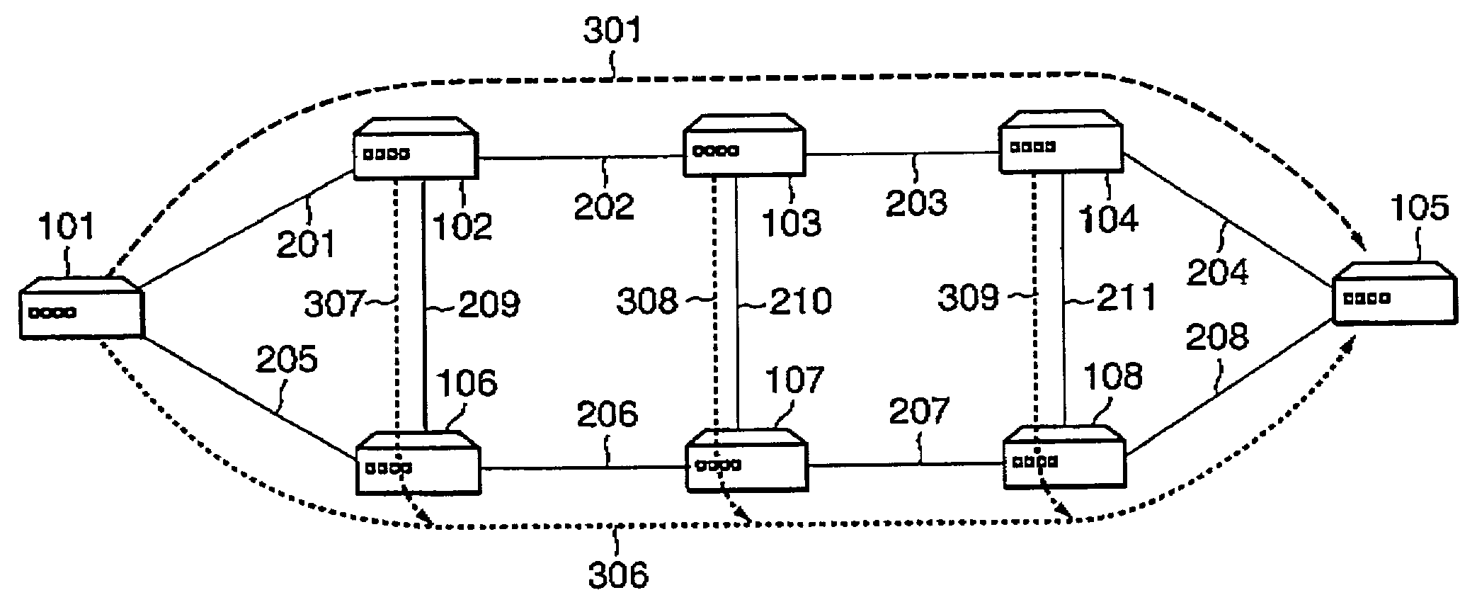
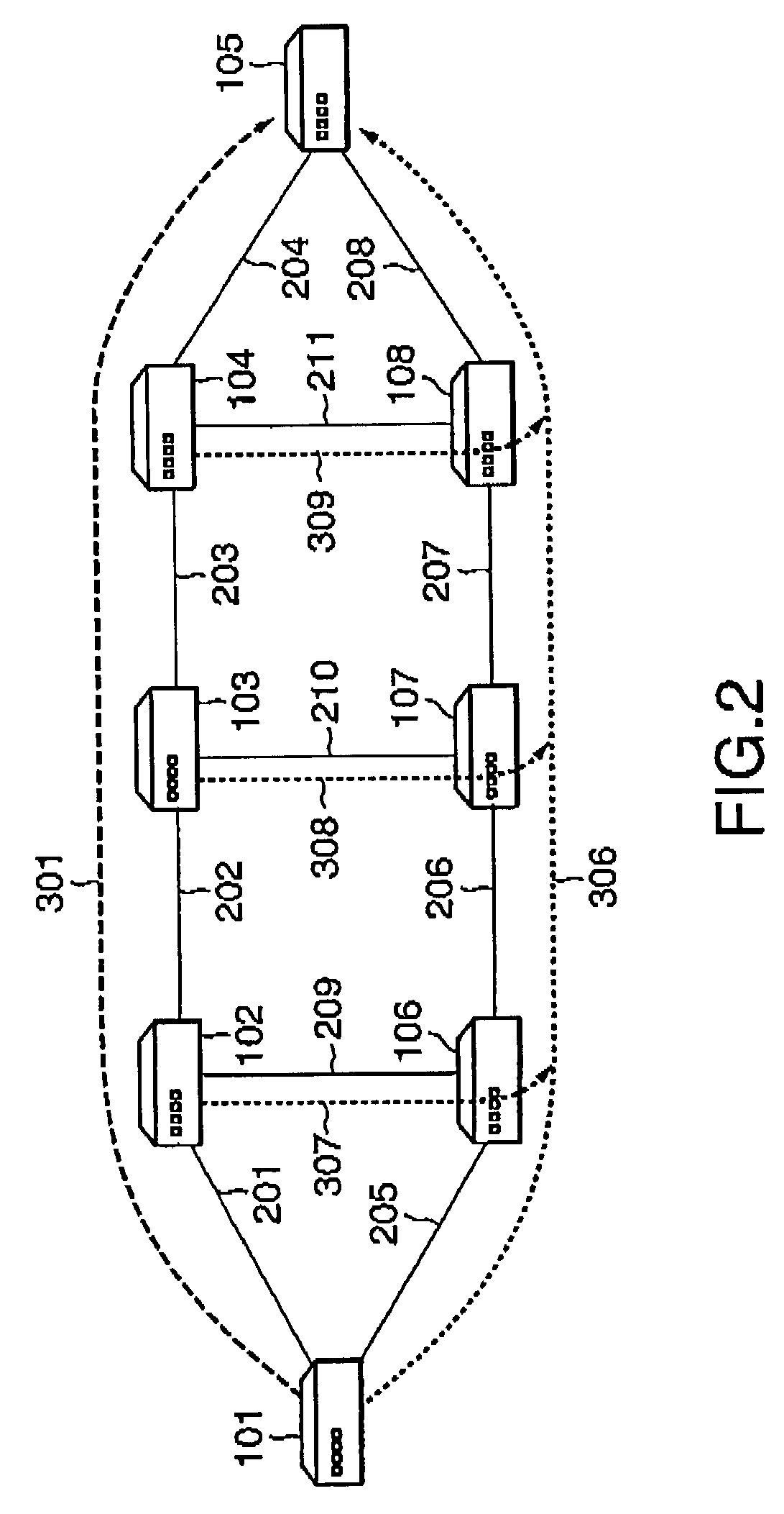
[0057]Referring to FIG. 5, when the setup of the main LSP is completed (step S101), the ingress LSR of the main LSP uses the route calculation section A12 to calculate a route for the backup LSP from the ingress LSR to the egress LSR of the main LSP (step S102). In the example of FIG. 2, when the setup of the main LSP 301 is completed, the LSR 101 calculates a route for the backup LSP from the LSR 101 up to the LSR 105.

[0058]In this case, a calculated route for the backup LSP must not share any link or node, between the ingress LSR and the egress LSR of the main LSP, with the main LSP. That is, the route for the backup LSP is calculated so as to be node-disjoint from the main LSP. In addition, w...

second embodiment

[0092]FIG. 13 illustrates an example of backup LSPs established in the

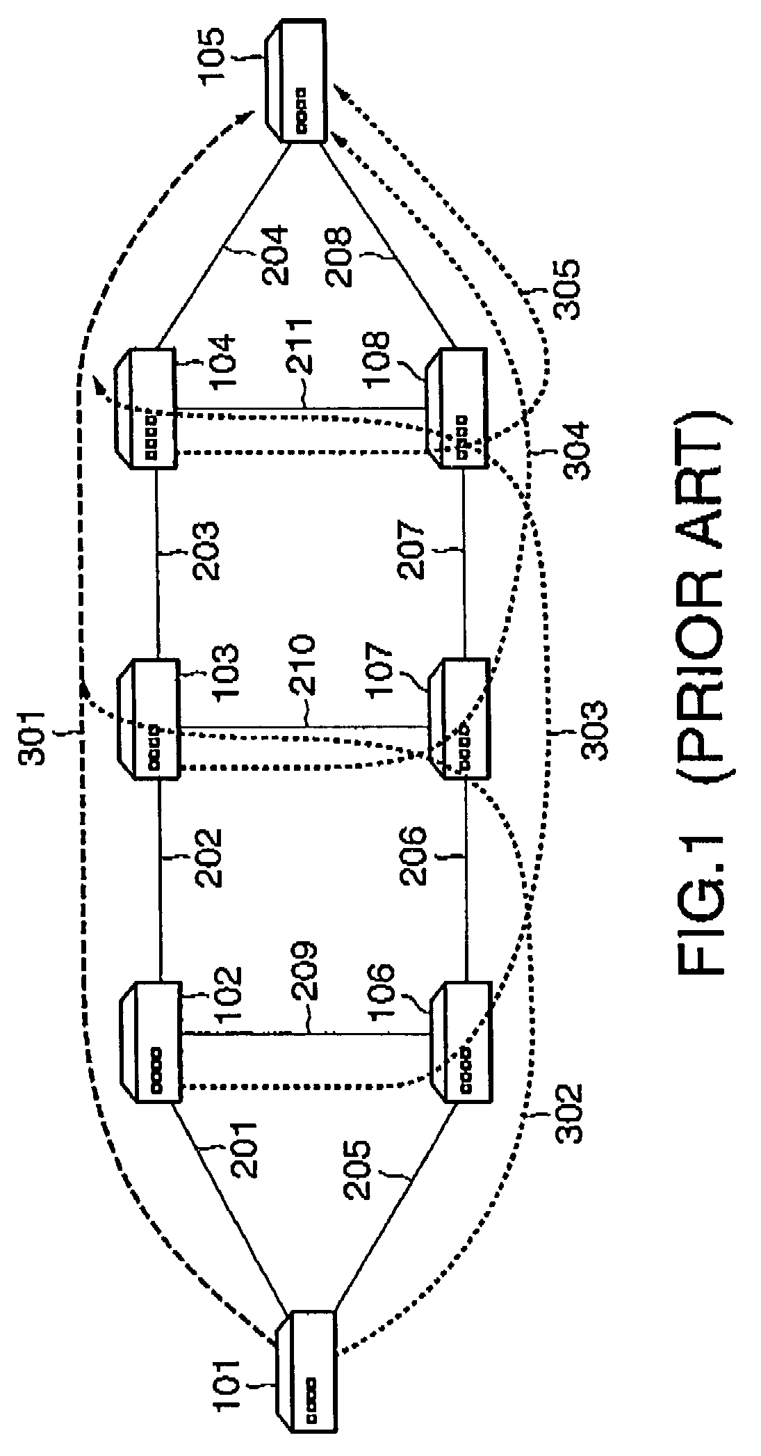
[0093]In FIG. 13, main LSPs 319 and 320 are established in the same network configuration as in FIG. 1. The main LSPs 319 and 320 have the same ingress LSR (LSR 101) and the same egress LSR (LSR 105), and are node-disjoint from each other. These two main LSPs 319 and 320 are commonly used for load balancing of traffic going through between the LSR 101 and the LSR 105. In such an arrangement, the main LSPs 319 and 320 are herein referred to as belonging to the same peer group.

[0094]In the second embodiment, a table stored in the LSP database A15 needs to include identifiers for distinguishing an LSP group belonging to the same peer group from an LSP group belonging to another peer group, in addition to the contents of the table shown in FIG. 4 of the first embodiment. That is, as shown in FIG. 14, an LSP group belonging to the same peer group is distinguished by using group identifiers (“groups GA, GB, . . . ,” sho...


PUM


Abstract

Backup LSPs (label switched path) are established from LSRs (label switching router) except the egress LSR of a main LSP. Each backup LSP is established between an LSR that functions as a starting node and the egress LSR so as not to include any link or node on the main LSP to be protected. When the backup LSP is established such that it merges into another pre-established backup LSP protecting the same main LSP, merging is performed at the LSR located at the merge point.

Description

BACKGROUND OF THE INVENTION[0001]1. Field of the Invention[0002]The present invention generally relates to a communication connection bypass method and to nodes and servers both of which implement the method. More particularly, the present invention relates to an improvement in minimizing loss of traffic flowing through a communication connection established in a connection-oriented network, in case of a node or link failure on the communication connection.[0003]2. Description of the Related Art[0004]Conventionally, such a communication connection bypass system has been used for the following purpose. In case of a node or link failure on a communication connection (main communication connection) in a connection-oriented network, a need exists for minimizing loss of the traffic flowing through the failed communication connection. This is implemented by switching a data transfer route to a pre-established backup communication connection that bypasses the failed node or link.[0005]One ...

Claims


Application Information

Patent Timeline
Patent Type & Authority Patents(United States)
IPC IPC(8): G06F11/00H04L1/22H04L45/128H04L45/24H04L45/247
CPCH04L1/22H04L45/02H04L45/128H04L43/0811H04L45/28H04L45/507H04L45/586H04L45/22H04L45/247
Inventor FUJITA, NORIHITO
Owner NEC CORP
Why Eureka
Try Eureka