Active impact protection system

a protection system and active technology, applied in the direction of liquid/fluent solid measurement, volume metering, instruments, etc., can solve the problems of increasing the chance that the device and/or its internal systems will be damaged, increasing the volume and weight of the device, and increasing the chance of accidental drop damage to the portable device. , to achieve the effect of reducing the peak impact force and great stopping distan

Inactive Publication Date: 2006-06-13
RAGNER GARY DEAN
View PDF9 Cites 237 Cited by
  • Summary
  • Abstract
  • Description
  • Claims
  • Application Information

AI Technical Summary

Problems solved by technology

Damage to portable devices from accidental dropping has always been a problem, whether it is your laptop computer you dropped or an item in a seagoing shipping container.
This results in large peak accelerations and large peak forces exerted on the device, which increases the chances that the device and / or its internal systems will be damaged.
Present systems include the use of padded corners on the device, but this adds significant volume and weight to the device, making it more bulky, which is a big disadvantage for modern electronic systems like laptop computers, PDAs, cellular phones, etc., where the smaller and lighter devices sell the best.
Sensors and a control circuit only activate the impact protection system when the system detects that the portable device is in a dangerous free-fall condition (a condition that could potentially cause damage to the portable device).
Other prior art impact protection systems do not have this luxury of large de-acceleration distances because they do not deploy their cushioning system away from the portable device itself.
Instead they have static cushions, which take up space and interfere with normal operation of the device if it were made large enough to provide the same impact protection as the applicant's impact protection system does.

Method used


Image

  • Active impact protection system
  • Active impact protection system
  • Active impact protection system

Examples


Embodiment Construction

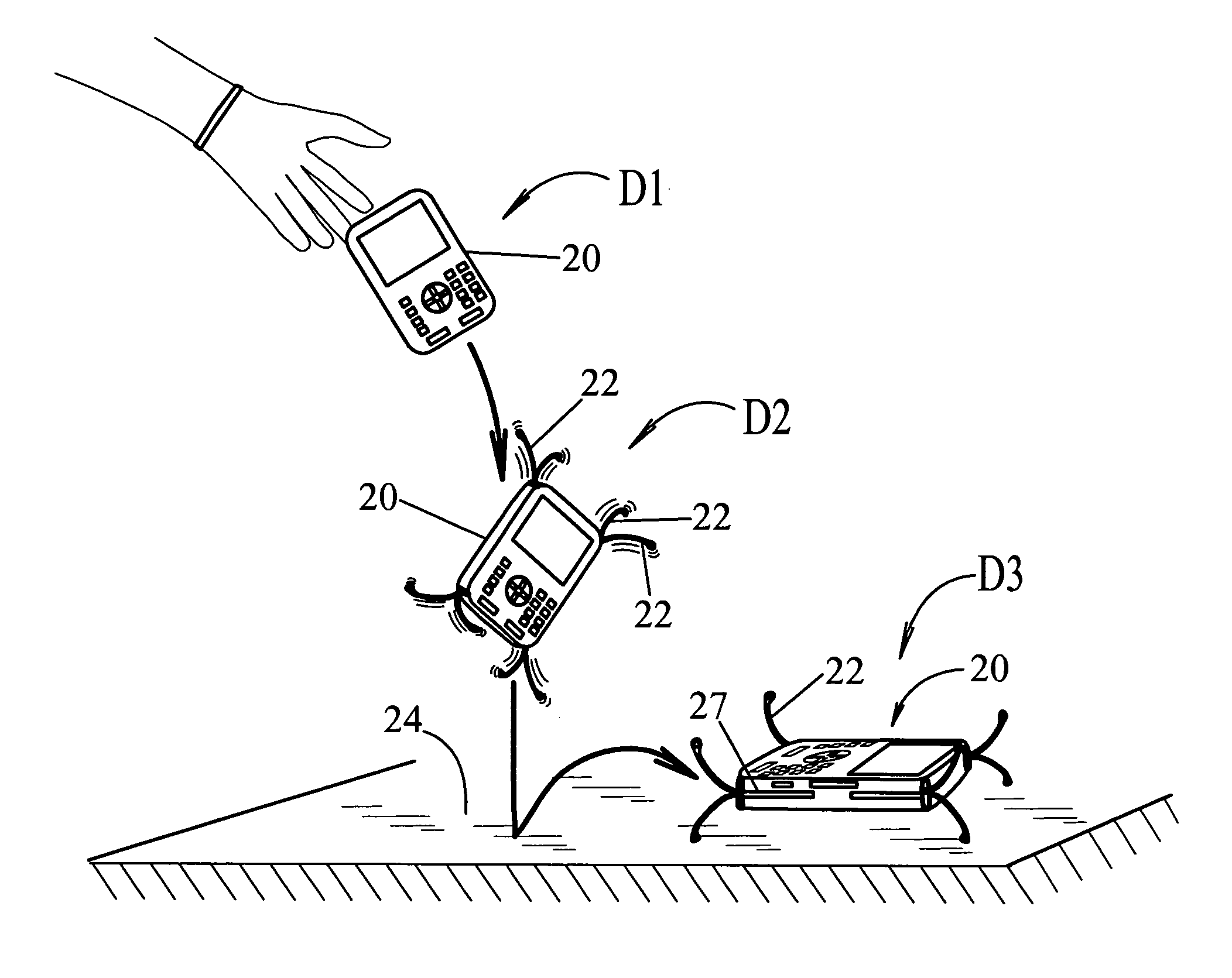
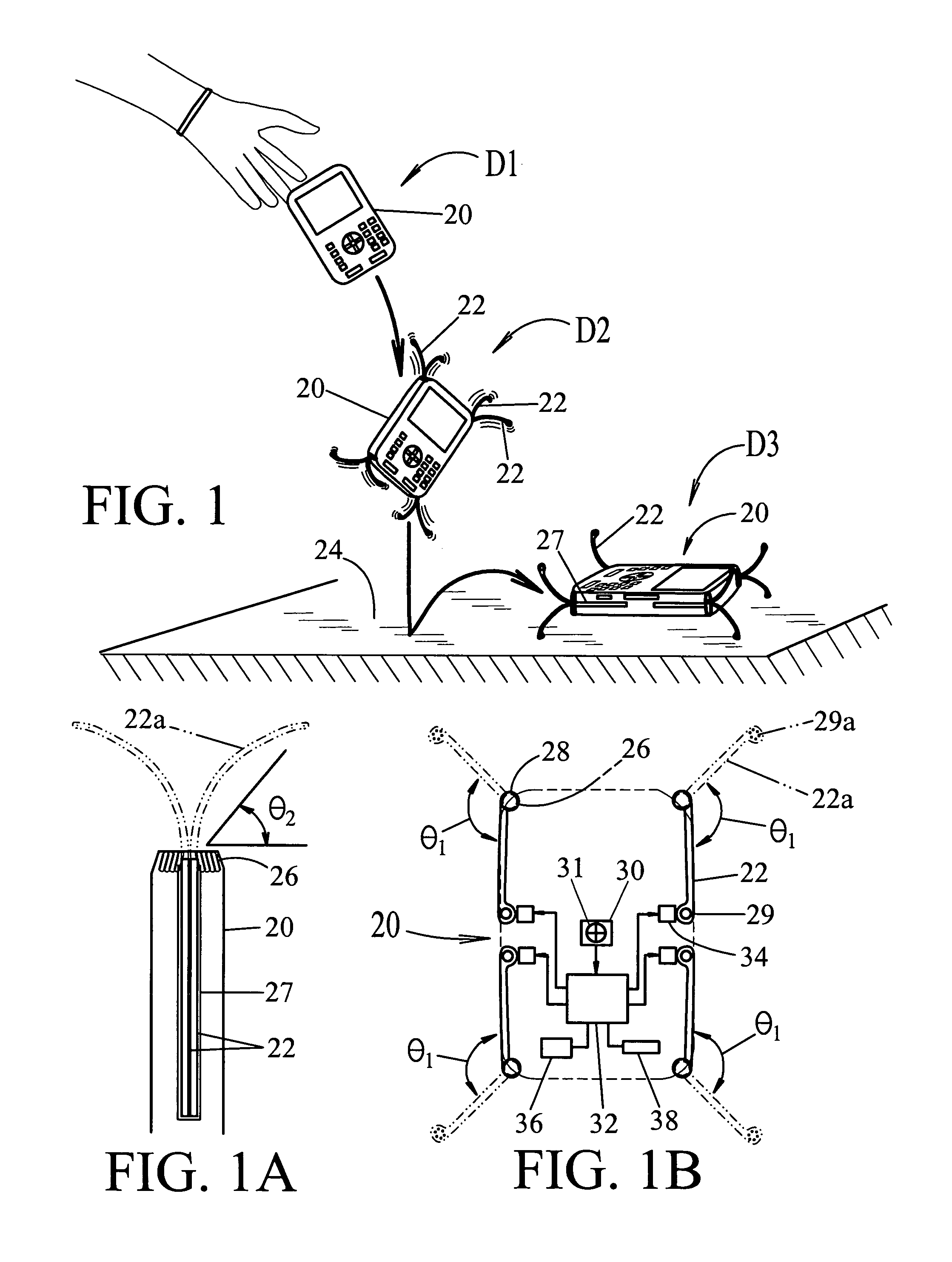
[0043]The basic concept for reducing impact forces on a free-falling device is to reduce the peak deceleration rate of the impact. On impact, forces build up to a maximum peak force and acceleration, and then quickly drop off as the object rebounds. The peak force and acceleration are what cause the damage. If the peak forces are reduce, the likelihood of damage is reduced. This is why people wear helmets when they ride a motorcycle: to provide that added inch of deceleration so that the peak acceleration and force on their head, in an impact, is greatly reduced, and also keep from cracking their head open. Likewise, this is the goal of the disclosed impact protection system, to significantly increase the distance over which the device is decelerated on impact, so that impact forces are greatly reduced.

[0044]Physics

[0045]For a hard cased PDA, the stopping distance on impact with a concrete floor may be only a couple millimeters, as the plastic or metal, bends and cracks. If thick ru...


PUM


Abstract

An impact protection system for a portable device, comprising a housing 20 with a plurality of impact absorbing arms 22 attached to housing 20 and having a retracted position and an extended position; an extension spring 26 connected to each arm provides forceful extension of the arms from their retracted position to their extended position; a free-fall detection sensor 30 defined within housing 20 for detecting dangerous free-fall conditions of the portable device and providing a signal to an activation controller 32 which is responsive to the free-fall detection sensor 30 and connected to the impact absorbing arms 22, whereby the arms are extended from their retracted position to their extended position upon detection of dangerous free-fall conditions to provide impact protection for the portable device.

Description

CROSS-REFERENCE TO RELATED APPLICATIONS[0001]This utility application claims priority from U.S. Provisional application Ser. No. 60 / 549,603, filed on Mar. 3, 2004, titled: “Active Impact Protection System” and its contents to be fully included within this Utility Application.BACKGROUND OF INVENTION[0002]The field of this invention relates to impact protection systems that protect fragile devices from impact loads (i.e. dropping from a height), and more specifically to actively deployed impact protection system when a free fall situation is detected, to reduce peak impact forces on the device.SUMMARY[0003]Damage to portable devices from accidental dropping has always been a problem, whether it is your laptop computer you dropped or an item in a seagoing shipping container. When a breakable device sustains a hard impact, or high acceleration force loads, the impact forces on the device can be many times the actual weight of the device. The sudden change in kinetic energy stored in the...

Claims


Application Information

Patent Timeline
Patent Type & Authority Patents(United States)
IPC IPC(8): G01F15/08
CPCH05K5/0086H04M1/185H04M1/0202H04M2250/12
Inventor RAGNER, GARY DEAN
Owner RAGNER GARY DEAN
Why Eureka
Try Eureka