Method and apparatus for stimulation of multiple formation intervals

a technology of multiple formation intervals and apparatus, which is applied in the direction of drilling casings, wellbore/well accessories, pipes, etc., can solve the problems of high treatment cost, high risk of complications, and bridge plugs that cannot be drilled out at great expens

Inactive Publication Date: 2006-06-13
EXXONMOBIL UPSTREAM RES CO
View PDF87 Cites 122 Cited by
  • Summary
  • Abstract
  • Description
  • Claims
  • Application Information

AI Technical Summary

Problems solved by technology

The major disadvantages are the high cost of treatment resulting from multiple trips into and out of the wellbore and the risk of complications resulting from so many operations in the well.
For example, a bridge plug can become stuck in the casing and need to be drilled out at great expense.
A further disadvantage is that the required wellbore clean-out operation may damage some of the successfully fractured intervals.
The disadvantages are that the sand plug does not give a perfect hydraulic seal and it can be difficult to remove from the wellbore at the end of all the fracture stimulations.
As before, additional wellbore operations increase costs, mechanical risks, and risks of damage to the fractured intervals.
If the pressure were too low, only the weakest portions of the formation would fracture.
The disadvantage is that limited entry fracturing often does not work well for thick intervals because the resulting fracture is frequently too narrow (the proppant cannot all be pumped away into the narrow fracture and remains in the wellbore), and the initial, high wellbore pressure may not last.
An additional concern is the potential for flow capacity into the wellbore to be limited by the small number of perforations.
Treatment and sealing theoretically proceeded zone by zone depending on relative breakdown pressures or permeabilities, but problems were frequently encountered with balls prematurely seating on one or more of the open perforations outside the targeted interval and with two or more zones being treated simultaneously.
Furthermore, this technique presumes that each perforation interval or sub-zone would break down and fracture at sufficiently different pressure so that each stage of treatment would enter only one set of perforations.
Costs are low because the process can typically be completed in one continuous operation, usually during just a few hours of a single day.
The primary disadvantage is the inability to be certain that only one set of perforations will fracture at a time so that the correct number of ball sealers are dropped at the end of each treatment stage.
Further disadvantages are lack of certainty that all of the perforated intervals will be treated and of the order in which these intervals are treated while the job is in progress.
When the order of zone treatment is not known or controlled, it is not possible to ensure that each individual zone is treated or that an individual stimulation treatment stage has been optimally designed for the targeted zone.
In some instances, it may not be possible to control the treatment such that individual zones are treated with single treatment stages.
However, various technical obstacles, including friction pressure losses, damage to sealing elements, depth control, running speed, and potential erosion of coiled tubing, currently limit deployment in deeper wells.
Depending on the length and diameter of the coiled tubing, the fluid viscosity, and the maximum allowable surface hardware working pressures, pump rates could be limited to just a few barrels per minute; which, depending on the characteristics of a specific subterranean formation, may not allow effective placement of proppant during hydraulic fracture treatments or effective dissolution of formation materials during acid stimulation treatments
Erosion of the coiled tubing could also be a problem as proppant-laden fluid is pumped down the interior of the coiled tubing at high velocity, including the portion of the coiled tubing that remains wound on the surface reel.
Most seal elements (e.g., “cup” seal technology) currently used in the coiled tubing stimulation operations described above could experience sealing problems or seal failure in deeper wells as the seals are run past a large number of perforations at the higher well temperatures associated with deeper wells.
Since the seals run in contact with or at a minimal clearance from the pipe wall, rough interior pipe surfaces and / or perforation burrs can damage the sealing elements.
Given safety issues surrounding nighttime operations, this slow running speed could result in multiple days being required to complete a stimulation job.
If any problems are encountered during the job, tripping in and out of the hole could be very costly because of the total operation times associated with the slow running speeds.
Depth control of the coiled tubing system and straddle-packer-like diversion tool also becomes more difficult as depth increases, such that placing the tool at the correct depth to successfully execute the stimulation operation may be difficult.
This problem is compounded by shooting the perforations before running the coiled tubing system in the hole.
The presence of multiple perforation sets open above the diversion tool can cause operational difficulties.
Also, it could be difficult to execute circulation operations if multiple perforation sets are open above the diversion tool.
For example, if the circulation pressures exceed the breakdown pressures associated with the perforations open above the diversion tool, the circulation may not be maintained with circulation fluid unintentionally lost to the formation.
However, using this approach would likely increase the time and cost associated with the operations because of slower pipe running speeds than those possible with coiled tubing.
These proposals all allow for only minimal fracture penetration surrounding the wellbore and are not adaptable to the needs of multi-stage hydraulic fracturing as described herein.

Method used


Image

  • Method and apparatus for stimulation of multiple formation intervals
  • Method and apparatus for stimulation of multiple formation intervals
  • Method and apparatus for stimulation of multiple formation intervals

Examples


second embodiment

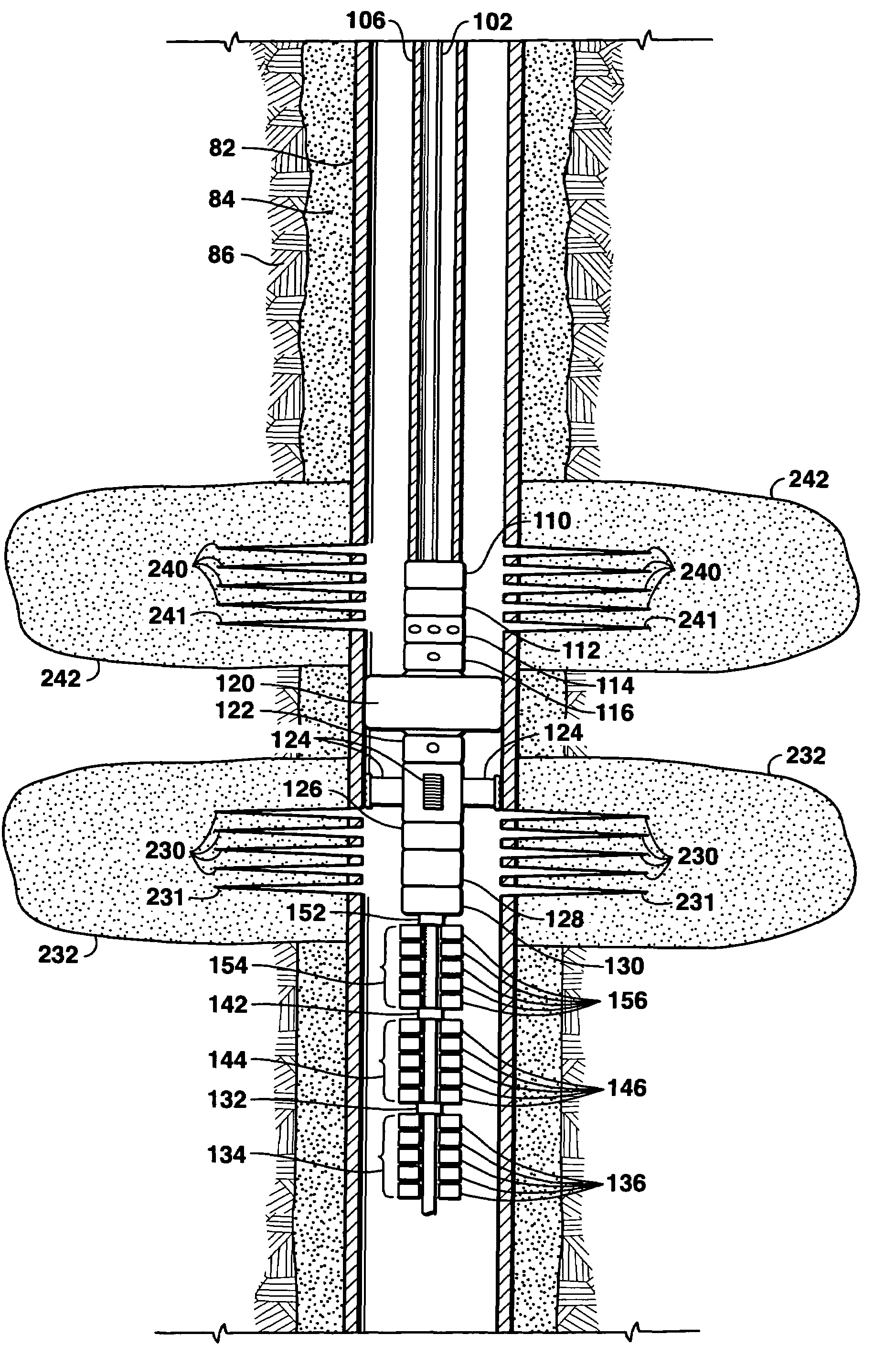
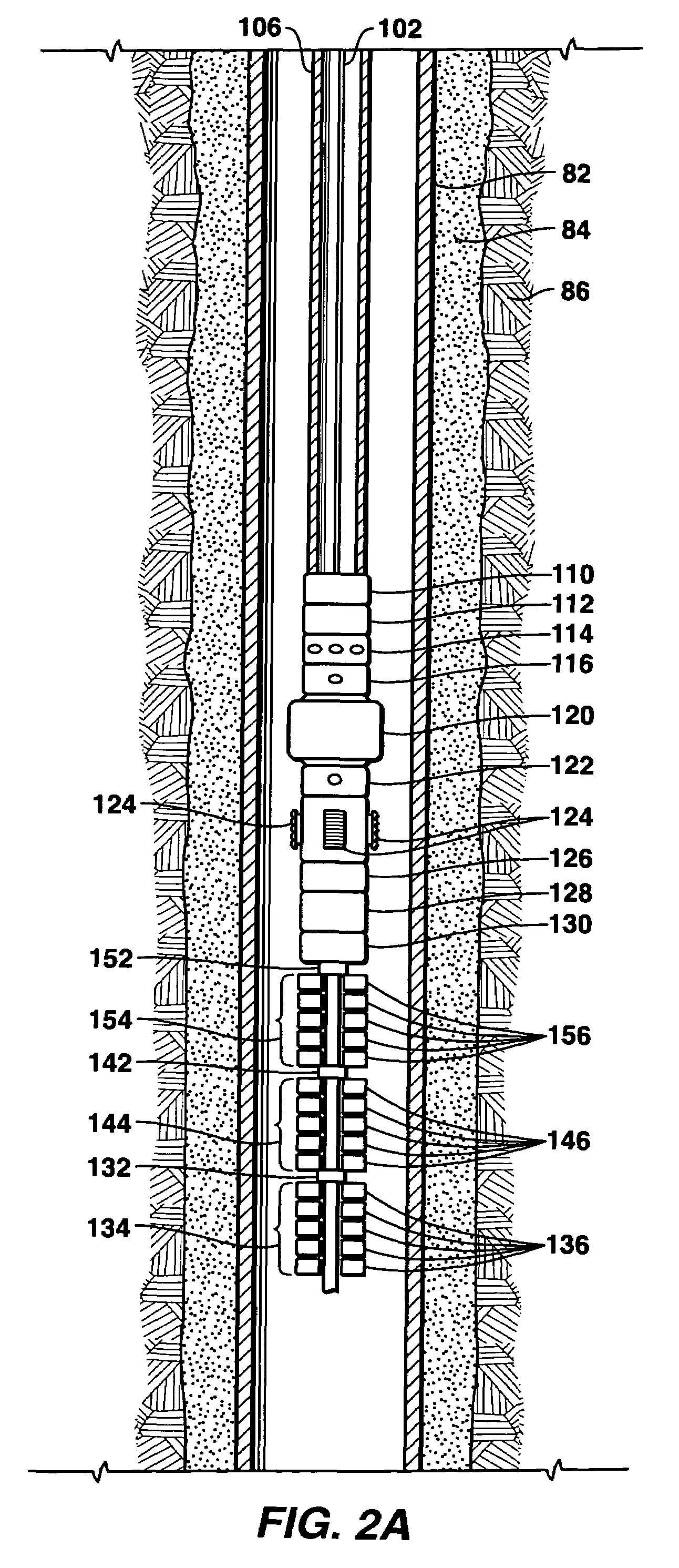
[0107]FIG. 5 illustrates the invention where coiled tubing is used as the deployment means and excess friction is not of concern and either proppant is not pumped during the job or use of proppant is not of concern. FIG. 5 shows that coiled tubing 106 is used to suspend the BHA and BHA components. In this embodiment, the individual zones are treated in sequential order from shallower wellbore locations to deeper wellbore locations. In this embodiment, as shown in FIG. 5, circulation port 114 is now placed below the inflatable, re-settable packer 120 such that treatment fluid may be pumped down the interior of coiled tubing 106, exit the circulation port 114, and be positively forced to enter the targeted perforations. As an illustration of the operations, FIG. 5 shows that the inflatable, re-settable packer 120 has been actuated and set below perforations 241 that are associated with a previous zone hydraulic fracture 242. The inflatable, re-settable packer 120 provides hydraulic is...

third embodiment

[0108]FIG. 6 illustrates the invention where coiled tubing is used as the deployment means and excess friction is not of concern and either proppant is not pumped during the job or use of proppant is not of concern. FIG. 6 shows that coiled tubing 106 is used to suspend the BHA and BHA components. In this embodiment, the individual zones may be treated in any order. In this embodiment, as shown in FIG. 6, a straddle-packer inflatable sealing mechanism 125 is used as the re-settable sealing mechanism and the circulation port 114 is now placed between the upper inflatable sealing element 121 and the lower inflatable sealing element 123. When the upper inflatable sealing element 121 and the lower inflatable sealing element 123 are actuated, treatment fluid may be pumped down the interior of coiled tubing 106 to exit the circulation port 114, and then be positively forced to enter the targeted perforations. As an illustration of the operations, FIG. 6 shows that the upper inflatable sea...

fourth embodiment

[0109]FIG. 7 illustrates the invention where a wireline 102 is used as the deployment means to suspend the BHA and BHA components. In this embodiment, the individual zones are treated in sequential order from deeper wellbore locations to shallower wellbore locations. In this embodiment, as shown in FIG. 7, treatment fluid may be pumped down the annulus between the wireline 102 and production casing wall 82 and be positively forced to enter the targeted perforations. In this embodiment, the inflatable re-settable packer 120 also contains an internal electrical pump system 117, powered by electrical energy transmitted downhole via the wireline, to inflate or deflate the inflatable, re-settable packer 120 using wellbore fluid. FIG. 7 shows that the inflatable, re-settable packer 120 has been actuated and set below the perforations 241 that are associated with the next zone to be fractured. The inflatable, re-settable packer 120 provides hydraulic isolation such that when treatment flui...


PUM


Abstract

The invention discloses methods of, as well as apparatus and systems for, perforating and treating multiple intervals of one or more subterranean formations intersected by a wellbore by deploying within said wellbore a bottom-hole assembly (“BHA”) having a perforating device and a sealing mechanism, wherein pressure communication is established between the portions of the wellbore above and below the sealing mechanism. The BHA is positioned within the wellbore such that the sealing mechanism, when actuated, establishes a hydraulic seal in the wellbore to positively force fluid to enter the perforations corresponding to the interval to be treated. A treating fluid is pumped down the wellbore and into the perforations created in the perforated interval. The sealing mechanism is released, and the steps are repeated for as many intervals as desired, without having to remove the BHA from said wellbore.

Description

RELATED U.S. APPLICATION DATA[0001]This Application is a continuation of application Ser. No. 10 / 278,519 filed Oct. 23, 2002, now U.S. Pat. No. 6,957,701 which is a divisional of application Ser. No. 10 / 085,518 filed Feb. 28, 2002, now U.S. Pat. No. 6,520,255 which is a continuation of application Ser. No. 09 / 781,597 filed Feb. 12, 2001, now U.S. Pat. No. 6,394,184, which claims the benefit of U.S. Provisional Patent Application Nos. 60 / 182,687 filed Feb. 15, 2000 and 60 / 244,258 filed Oct. 30, 2000.FIELD OF THE INVENTION[0002]This invention relates generally to the field of perforating and treating subterranean formations to increase the production of oil and gas therefrom. More specifically, the invention provides an apparatus and a method for perforating and treating multiple intervals without the necessity of removing equipment from the wellbore between steps or stages.BACKGROUND OF THE INVENTION[0003]When a hydrocarbon-bearing, subterranean reservoir formation does not have enou...

Claims


Application Information

Patent Timeline
Patent Type & Authority Patents(United States)
IPC IPC(8): E21B33/124E21B33/129E21B43/119E21B43/267E21B17/20E21B33/12E21B43/117E21B43/26
CPCE21B17/203E21B33/12E21B47/04E21B43/26E21B43/117E21B43/2605E21B43/27
Inventor TOLMAN, RANDY C.CARLSON, LAWRENCE O.KINISON, DAVID A.NYGAARD, KRIS J.GOSS, GLENN S.SOREM, WILLIAM A.SHAFER, LEE L.
Owner EXXONMOBIL UPSTREAM RES CO
Why Eureka
Try Eureka