Scan line alignment in raster pattern

Active Publication Date: 2006-06-13
MICROVISION
View PDF1 Cites 19 Cited by
  • Summary
  • Abstract
  • Description
  • Claims
  • Application Information

AI Technical Summary

Benefits of technology

[0012]Still another object of this invention is to eliminate image calibration in image projection arrangements.
[0014]An additional object is to provide a miniature, compact, lightweight, and portable color image projection arrangement useful in many instruments of different form factors.FEATURES OF THE INVENTION

Problems solved by technology

However, the known image projection systems project the image with limited resolution, typically less than a fourth of video-graphics-array (VGA) quality of 640×480 pixels, and often suffer from misalignment among the scan lines which produces images offset from one another.
Experience has shown, however, that the known feedback circuits are not altogether satisfactory.
Unfortunately, this calibration does not accommodate changes in temperature and ageing of the circuit components and, hence, must be repeated from time to time, a procedure which a consumer may likely be unwilling to perform.

Method used


Image

  • Scan line alignment in raster pattern
  • Scan line alignment in raster pattern
  • Scan line alignment in raster pattern

Examples


Embodiment Construction

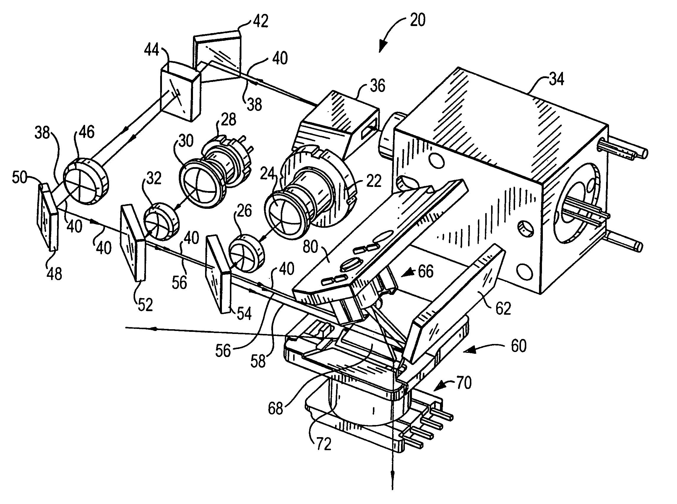
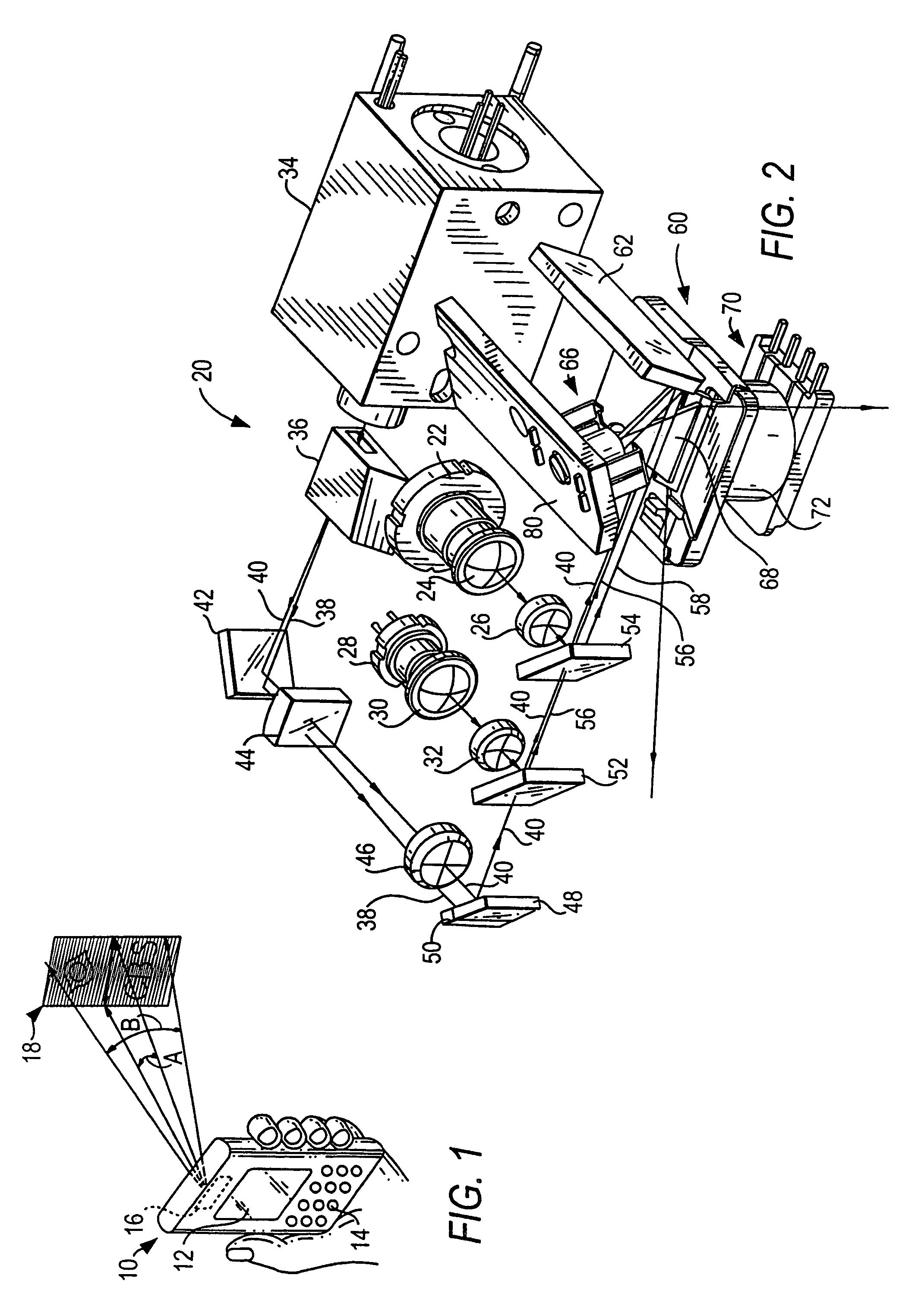
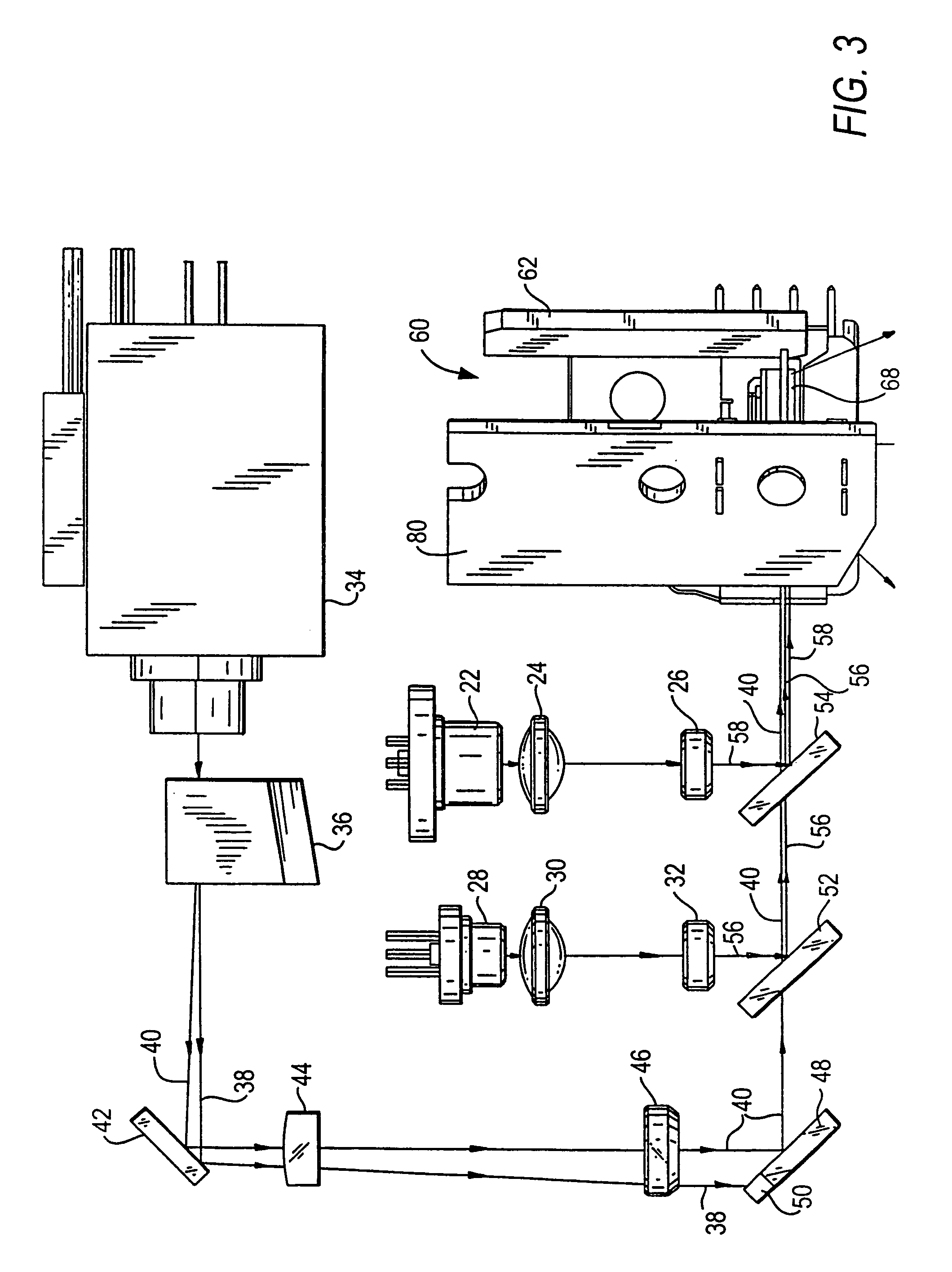
[0042]Reference numeral 10 in FIG. 1 generally identifies a hand-held instrument, for example, a personal digital assistant, in which a lightweight, compact, image projection arrangement 20, as shown in FIG. 2, is mounted and operative for projecting a two-dimensional color image at a variable distance from the instrument. By way of example, an image 18 is situated within a working range of distances relative to the instrument 10.

[0043]As shown in FIG. 1, the image 18 extends over an optical horizontal scan angle A extending along the horizontal direction, and over an optical vertical scan angle B extending along the vertical direction, of the image. As described below, the image is comprised of illuminated and non-illuminated pixels on a raster pattern of scan lines swept by a scanner in the arrangement 20.

[0044]The parallelepiped shape of the instrument 10 represents just one form factor of a housing in which the arrangement 20 may be implemented. The instrument can be shaped as a...


PUM


Abstract

A lightweight, compact image projection module, especially for mounting in a housing having a light-transmissive window, is operative for causing selected pixels in a raster pattern to be illuminated to produce an image of high resolution of VGA quality in color. A data signal on a pattern of odd and even scan lines in the pattern is synchronized with movement of a scan mirror operative to sweep a light beam along each scan line to align all the scan lines.

Description

BACKGROUND OF THE INVENTION[0001]1. Field of the Invention[0002]The present invention generally relates to scan line alignment in a raster pattern and to an arrangement for, and a method of, synchronizing a data signal on a pattern of odd and even scan lines with movement of a scan mirror operative for sweeping a light beam along each scan line, especially for use in a color image projection system operative for projecting a two-dimensional image in color while maintaining low power consumption, high resolution, miniature compact size, quiet operation and minimal vibration.[0003]2. Description of the Related Art[0004]It is generally known to project a two-dimensional image on a screen based on a pair of scan mirrors which oscillate in mutually orthogonal directions to sweep a laser beam over a raster pattern consisting of odd scan lines, for example, swept from left-to-right across the screen, and even scan lines, for example, swept from right-to-left across the screen. Each scan li...

Claims


Application Information

Patent Timeline
IPC IPC(8): G06K7/10G06K7/14
CPCH04N9/3129H04N3/08
Inventor YAVID, DMITRIY
Owner MICROVISION
Why Eureka
Try Eureka