Method and apparatus for enhanced oil recovery by injection of a micro-dispersed gas-liquid mixture into the oil-bearing formation

a gas-liquid mixture and micro-dispersion technology, which is applied in the direction of separation process, transportation and packaging, dispersed particle separation, etc., can solve the problems of difficult to achieve under normal oil field conditions, low stability of gas-water mixture, and high equipment requirements, so as to achieve enhanced recovery and enhanced recovery

Inactive Publication Date: 2006-06-13
BORTKEVITCH SERGEY V +3
View PDF8 Cites 37 Cited by
  • Summary
  • Abstract
  • Description
  • Claims
  • Application Information

AI Technical Summary

Benefits of technology

[0006]It is further object of present invention to provide a method for enhanced recovery of a petroleum fluid produced by a reservoir, comprising injection of a sweep fluid into an oil-bearing reservoir through an injection well, the sweep fluid comprising a micro-dispersed gas-liquid mixture having size of gas bubbles not exceeding 30 percent of an average diameter of the pores of said oil-bearing reservoir under the pressure in gas injection line in the range of ±20 percent of the pressure in liquid injection line and gas content accounting for 10-40 percent of a micro-dispersed gas-liquid mixture bulk volume.
[0007]It is another object of present invention to provide a method for enhanced recovery of a petroleum fluid produced by a reservoir in which the injection of a micro-dispersed gas-liquid mixture and liquid without gas carries out intermittently.

Problems solved by technology

However such a technique requires sophisticated equipment as the parameters of injection must be accurately fulfilled which is difficult to achieve under normal oil field conditions.
However, the gas-water mixture stability is low because the size of the gas bubbles cannot be controlled in accordance with these inventions.
In addition, a gas / water mixture requires additional compression relative to injection pressure as compared to a water-only system, thus extra energy is needed.

Method used


Image

  • Method and apparatus for enhanced oil recovery by injection of a micro-dispersed gas-liquid mixture into the oil-bearing formation
  • Method and apparatus for enhanced oil recovery by injection of a micro-dispersed gas-liquid mixture into the oil-bearing formation

Examples


Embodiment Construction

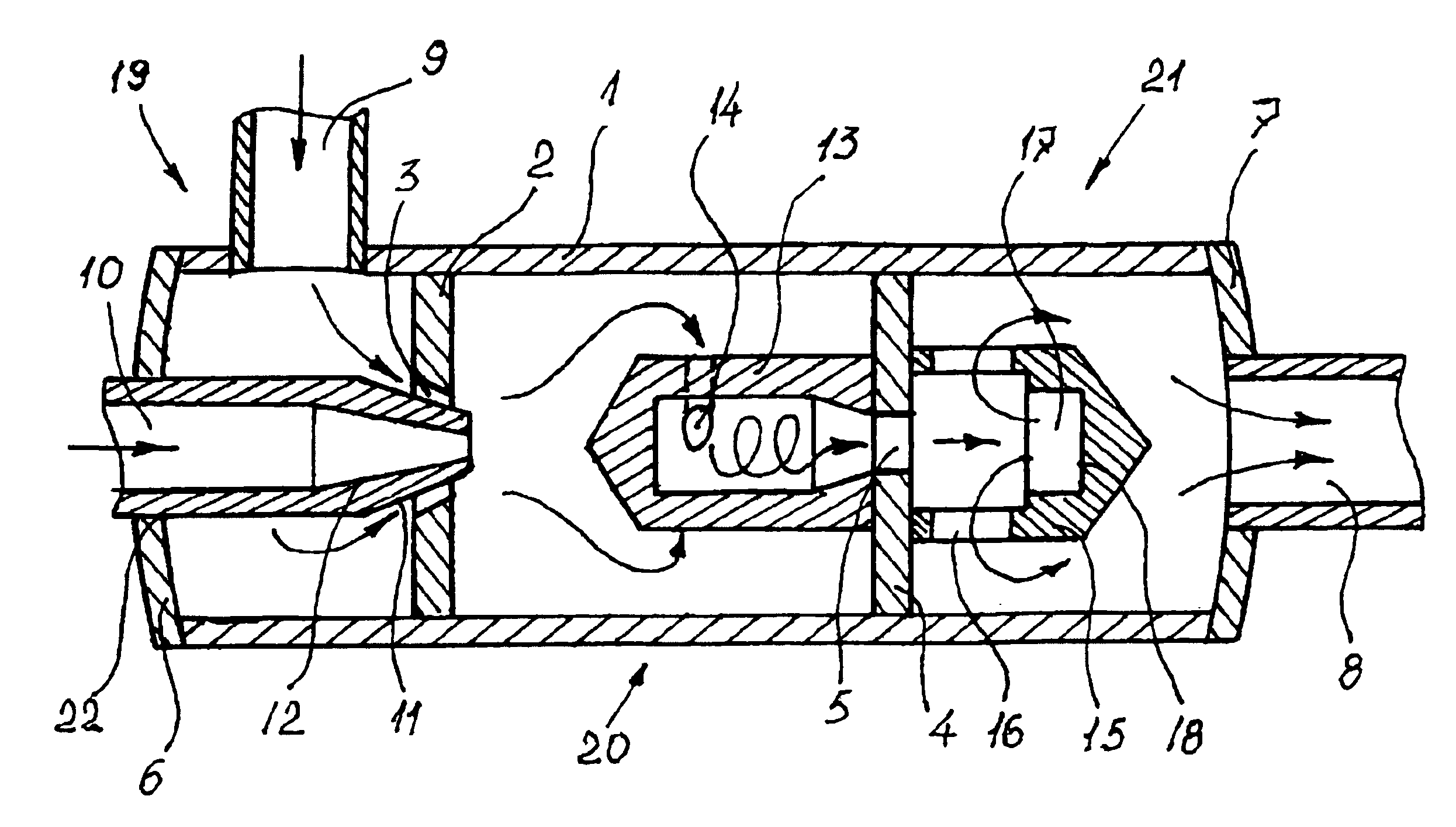
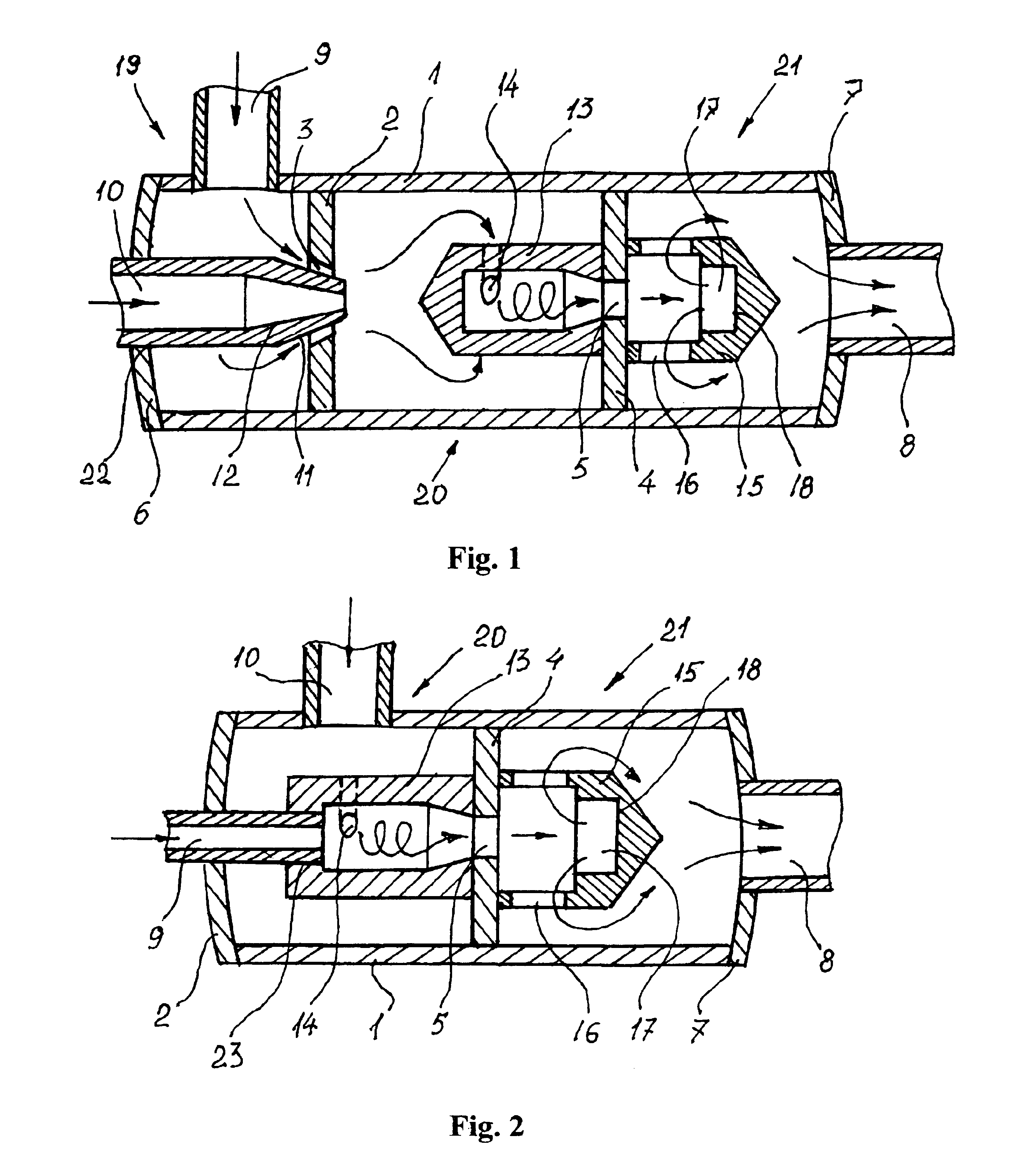
[0011]Referring to FIG. 1, there is shown a device for producing a micro-dispersed gas-liquid mixture. The device includes a gas-liquid ejector unit 19, a cavitation unit 20 and a jet dispersing unit 21 installed in a sequence in a cylindrical housing 1 which in turn includes bottom 6 and top 7 covers and also has a first partition 2 having a conical orifice 3 separating a gas-liquid ejector unit 19 from a cavitation unit 20 and a second partition 4 having an orifice 5 separating a cavitation unit 20 from a jet dispersing unit 21. The gas-liquid ejector unit 19 has an inlet nozzle 10 located at the cylindrical housing bottom cover 6 for liquid and the inlet 9 located on side surface of housing 1 for gas. The inlet nozzle 10 for liquid is a nozzle the top both outside 11 and inside 12 parts of which are adapted to the conical orifice 3 of the first partition 2 to provide a required flowrate of an ejected gas through the gas inlet 9. The gas-liquid ejector unit 19 communicates through...


PUM

PropertyMeasurementUnit
diameteraaaaaaaaaa
interfacial tensionaaaaaaaaaa
pressureaaaaaaaaaa

Abstract

The method and apparatus for making a micro-dispersed gas-liquid mixture which includes a gas-liquid ejector unit, a cavitation unit and a jet dispersing unit installed in a sequence. All above referenced units are installed into a cylindrical housing which in turn includes bottom and top covers and also has a first partition having a conical orifice separating a gas-liquid ejector unit from a cavitation unit and a second partition separating a cavitation unit from a jet dispersing unit. The gas-liquid ejector unit has an inlet located at the bottom of the cylindrical housing for liquid and the inlet located on side surface of housing for gas, these being between bottom cover of the housing and the first partition. In addition, the inlet for liquid is a nozzle the top having both outside and inside parts of which are adapted to the conical orifice of first partition to provide a required flow-rate of an ejected gas through the gas inlet. The gas-liquid ejector unit communicates through the conical orifice of the first partition with a cavitation unit comprising a hollow cylindrical cavitation chamber having at least one tangential inlet allowing a gas-liquid mixture from a gas-liquid ejector unit to flow inside the hollow cylindrical cavitation chamber for breaking of gas bubbles and further to a jet dispersing unit through an orifice of second partition for additional dispersing and homogenization. The jet dispersing unit comprises a hollow cylindrical dispersing chamber attached to the second partition and communicates with the injection well through an outlet located at the top cover of the cylindrical housing. In addition, the hollow cylindrical dispersing chamber has at least one outlet channel and a hollow dip at the bottom of the hollow cylindrical dispersing chamber.

Description

TECHNICAL FIELD[0001]The present invention relates to an enhanced oil recovery process with injection of gas-liquid mixture into a reservoir. The process according to the invention finds application notably for improving the displacement of petroleum fluids towards producing wells and therefore for increasing the recovery ratio of the usable fluids, oil and gas, initially in-place in the rock.BACKGROUND OF INVENTION[0002]The Water-Alternating-Gas (WAG) method where water is combined with gas is a well-known Enhanced Oil Recovery (EOR) method. According to the WAG method, water and gas are injected in succession for as long as petroleum fluids are being produced economically. The purpose of the water slugs is to reduce the mobility of the gas and to widen the swept zone. Many improvements have been proposed for this technique, for example in one method surfactants can be added to the water in order to decrease the water-oil interfacial tension and in another method a foaming agent is...

Claims


Application Information

Patent Timeline
Patent Type & Authority Patents(United States)
IPC IPC(8): B01F3/04B01F5/00B01F5/02B01F5/04B01F5/06
CPCB01F3/0446B01F5/0057B01F5/0268B01F5/0415B01F5/0682B01F5/0688B01F5/0689B01F5/0428Y10S261/75B01F23/232B01F25/10B01F25/25B01F25/3121B01F25/31242B01F25/45B01F25/45211B01F25/4521
Inventor BORTKEVITCH, SERGEY V.KOSTROV, SERGEY A.SAVITSKY, NICKOLAY V.WOODEN, WILLIAM O.
Owner BORTKEVITCH SERGEY V
Why Eureka
Try Eureka