
Workpiece processing and liquid droplet ejection inspection apparatus

a technology of liquid droplet ejection and inspection apparatus, which is applied in the direction of recording apparatus, inking apparatus, instruments, etc., can solve the problems that the inspection cannot be conducted accurately on the “irregular speed” alone, and the appropriate measure cannot be taken for each factor separately

Inactive Publication Date: 2006-06-13
SEIKO EPSON CORP
View PDF3 Cites 11 Cited by
  • Summary
  • Abstract
  • Description
  • Claims
  • Application Information

AI Technical Summary

Benefits of technology

[0007]It is an advantage of this invention to provide a processing accuracy inspection apparatus of a workpiece processing apparatus which is capable of distinguishing between bad or poor accuracy due to mechanical accuracy of a moving mechanism and the bad accuracy due to processing accuracy of a processing mechanism. It is also an advantage of this invention to provide an inspection apparatus for inspecting a drawing accuracy of a liquid droplet ejection apparatus, a liquid droplet ejection apparatus, a workpiece, an electro-optic device, a method of manufacturing an electro-optic device, and an electronic equipment.
[0018]According to the above-described arrangement, it is not required to generate stippling timing (data) exclusively used for the stippling means. In addition, a visual comparison can be easily made between the stippled dots and the drawn dots.
[0020]According to the above-described arrangement, theoretically, the drawn dots and the stippled dots are drawn along the same line in a moving direction of the function liquid droplet ejection head and the stippling means. Thus, a comparison can be easily made between the drawn dots and the stippled dots without correction thereof. Accordingly, bad accuracy can be recognized instantly.
[0025]According to the above-described arrangement, an appropriate measure can be taken based on an inspection result from the drawing accuracy inspection apparatus. Namely, if bad accuracy is caused by the moving mechanism, measure can be taken, with respect to an “irregular speed,” by controlling the speed of a motor (actuator) every second by corrected pulse widths and the like and, with respect to undulation, by correcting the place of disposing the moving mechanism or by replacing it. On the other hand, if bad accuracy is caused by the function liquid droplet ejection head, measure can be taken, with respect to “slanted ejection” of the function liquid, by cleaning of replacing the ejection head. Alternatively, if bad accuracy is caused by “inclination” of the ejection head, the ejection head is correctly re-attached to a carriage. Further, changes in an ejection or flight speed can be resolved by correcting the ejection timing.
[0028]According to the above-described arrangement, accuracy inspection can be easily carried out before primary drawing is performed onto the workpiece by the liquid droplet ejection apparatus. For example, with the liquid droplet ejection apparatus which performs drawing in an inert gas atmosphere, the inspection can be carried out without destroying the atmosphere. Preferably, the stippling area and the drawing area for inspection are set to unnecessary portions (non-drawing areas) of the workpiece, such as a peripheral portion or a portion to be cut off ultimately.

Problems solved by technology

Thus, inspection cannot be conducted accurately on the “irregular speed” alone.
Therefore, there has been a problem in that an appropriate measure cannot be taken for each of the factors separately.

Method used


Image

  • Workpiece processing and liquid droplet ejection inspection apparatus
  • Workpiece processing and liquid droplet ejection inspection apparatus
  • Workpiece processing and liquid droplet ejection inspection apparatus

Examples


Embodiment Construction

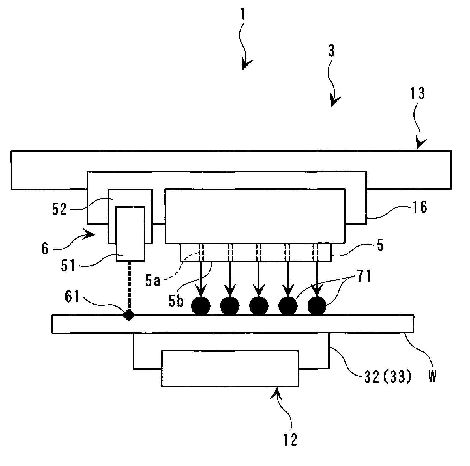
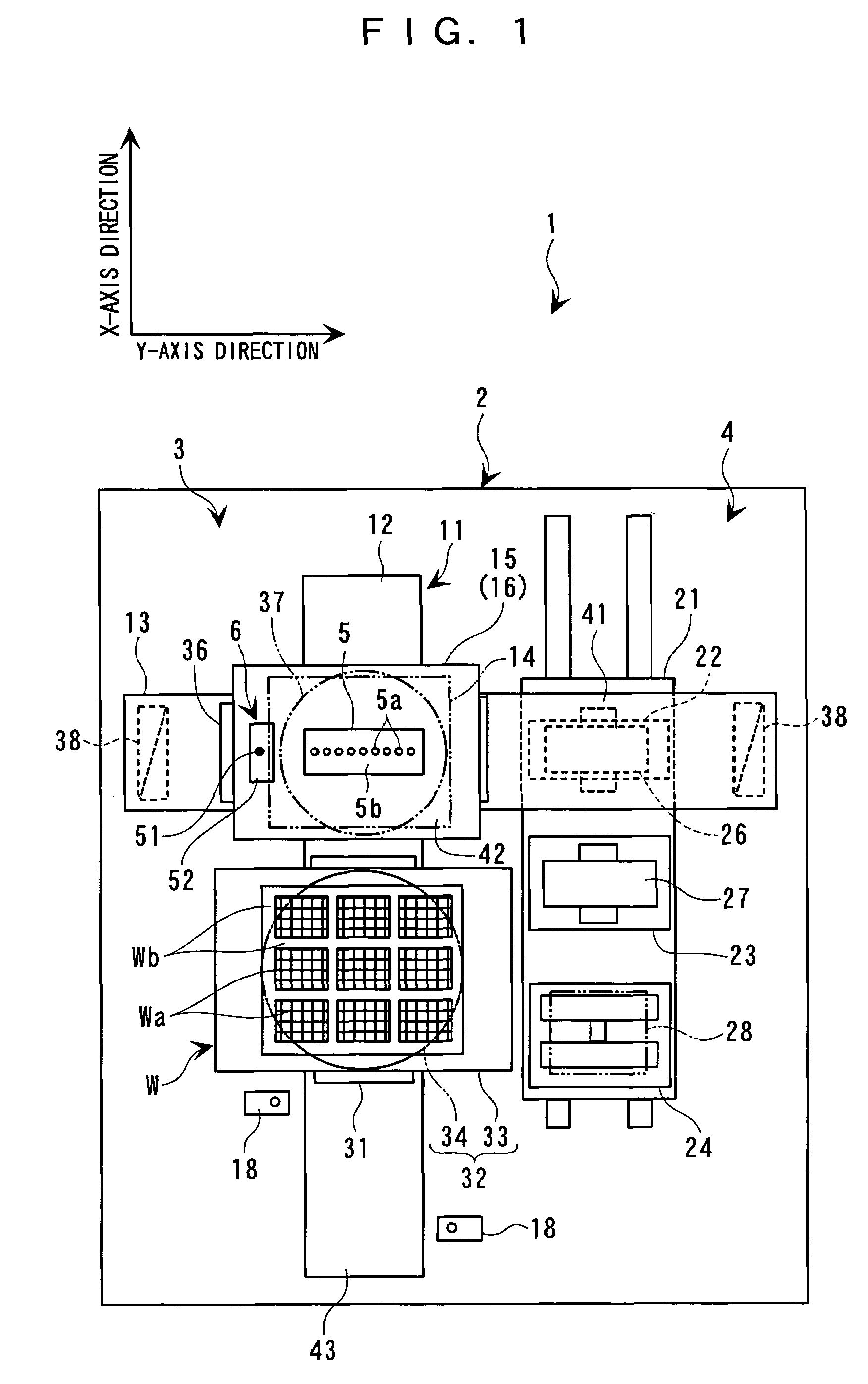
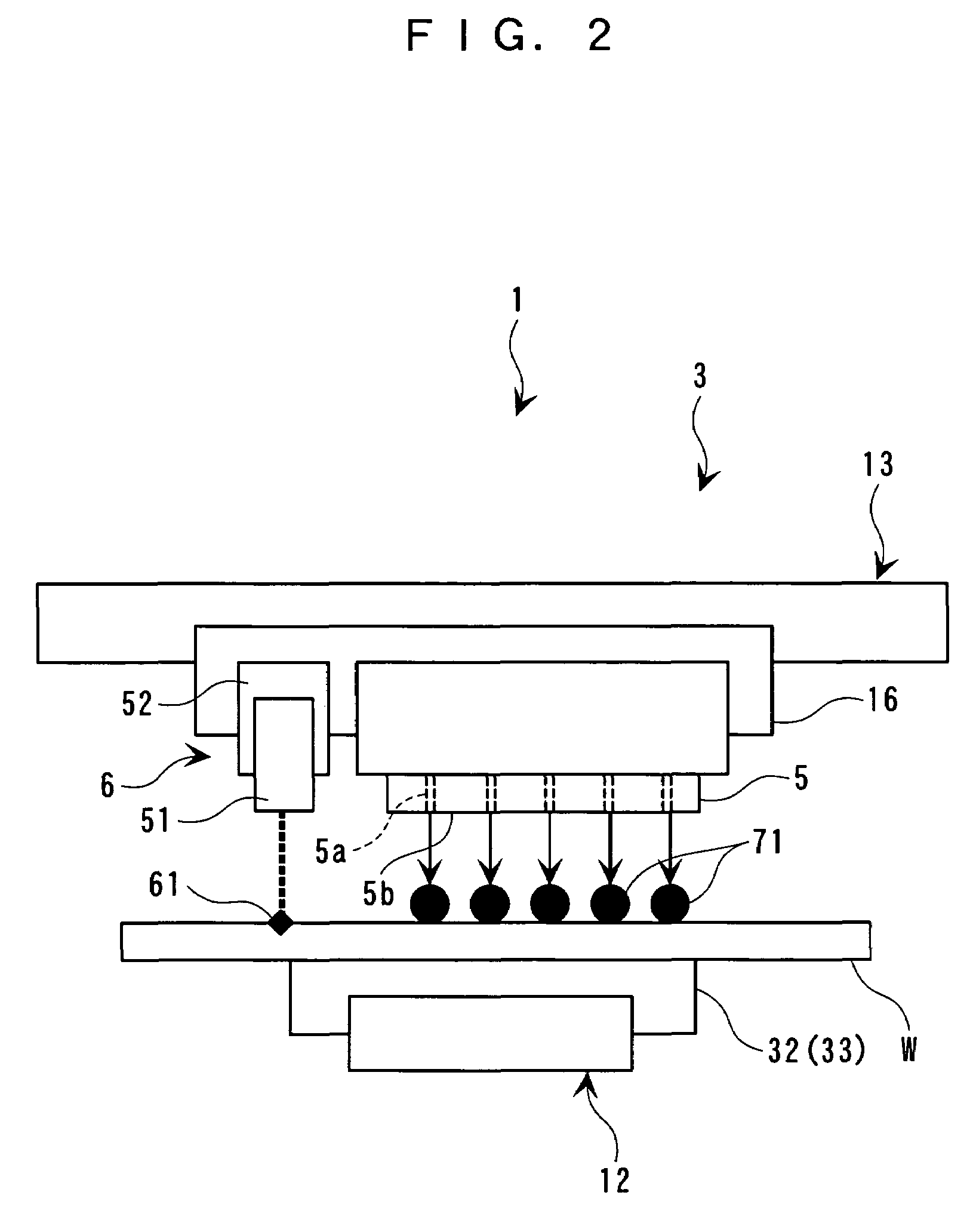
[0045]With reference to the attached drawings, a description will be made about a case in which an inspection apparatus for inspecting a processing accuracy of a workpiece processing apparatus as well as an inspection apparatus for inspecting a drawing accuracy of a liquid droplet ejection apparatus are applied to a liquid droplet ejection apparatus. The liquid droplet ejection apparatus in this embodiment employs a function liquid droplet ejection head (or heads) and ejects a function liquid (or liquids) toward a substrate which is a workpiece, thereby forming a deposited portion (film-forming portion) on the substrate. This film-forming or depositing work is also referred to as a workpiece processing (details thereof will be described hereinafter).

[0046]As shown in a schematic plan view of FIG. 1 and a schematic front view of FIG. 2, a liquid droplet ejection apparatus 1 of this embodiment includes a stand 2, a drawing apparatus 3 mounted over an entire area of the stand 2, and a ...


PUM

PropertyMeasurementUnit
Coloraaaaaaaaaa
Areaaaaaaaaaaa
Frequencyaaaaaaaaaa

Abstract

An apparatus for inspecting drawing accuracy in a liquid droplet ejection apparatus performs drawing by ejecting a function liquid droplet while moving a function liquid droplet ejection head relative to a workpiece by using a moving mechanism. In response to the relative movement, a laser irradiating mechanism performs visually recognizable stippling on the workpiece by irradiating coherent light thereon. A control part drives the laser irradiating mechanism for stippling at a predetermined frequency timing.

Description

RELATED APPLICATIONS[0001]This application claims priority to Japanese Patent Application No. filed which is hereby incorporated by reference in its entirety.BACKGROUND OF THE INVENTION[0002]1. Field of the Invention[0003]This invention relates to an inspection apparatus for inspecting a processing accuracy of a workpiece processing apparatus. This inspection apparatus inspects the landing accuracy of a function liquid droplet as ejected from a function liquid droplet ejection head, as represented by an ink jet head, in a liquid droplet ejection apparatus toward a workpiece such as a substrate. This invention also relates to an inspection apparatus for inspecting a drawing (image-forming) accuracy of a liquid droplet ejection apparatus, a liquid droplet ejection apparatus, a workpiece, an electro-optic device, a method of manufacturing an electrooptic device, and an electronic equipment.[0004]2. Description of the Related Art[0005]As this kind of conventional inspection apparatus as...

Claims


Application Information

Patent Timeline
IPC IPC(8): B41J23/00B41J2/01B05C5/00B05C11/00B41J29/393B41J29/46
CPCB41J29/393B41J2202/09B41J2/01
Inventor IWATA, YUJI
Owner SEIKO EPSON CORP
Learn More