Display apparatus and image pickup apparatus

a technology which is applied in the field of display apparatus and image pickup apparatus, can solve the problems of large amount of time and labor to produce, and the viewable position is very limited, and achieve the effect of improving resolution

Active Publication Date: 2006-06-13
HITACHI LTD
View PDF6 Cites 34 Cited by
  • Summary
  • Abstract
  • Description
  • Claims
  • Application Information

AI Technical Summary

Benefits of technology

[0009]In view of these problems, an object of the present invention is to provide a display apparatus and an image-pickup apparatus that enables a person to view clear three-dimensional images of high resolution from any direction without caring about the timing of the projection of two-dimensional images.

Problems solved by technology

This necessitates great number of two-dimensional images, requiring great amount of time and labor to produce them, and also a memory storage of large capacity to store the two-dimensional image data.
In the technology described in Japan Patent Laid-open No. 2002-271820 mentioned above, for displaying a three-dimensional image using two-dimensional images read from the cylindrical film described above, an intricate means to read images sequentially from such a cylindrical film is required, and since these images read from the cylindrical film are imaged in a space, a clear three-dimensional image is visible only at this imaging point, making viewable position very limited.

Method used


Image

  • Display apparatus and image pickup apparatus
  • Display apparatus and image pickup apparatus
  • Display apparatus and image pickup apparatus

Examples


first embodiment

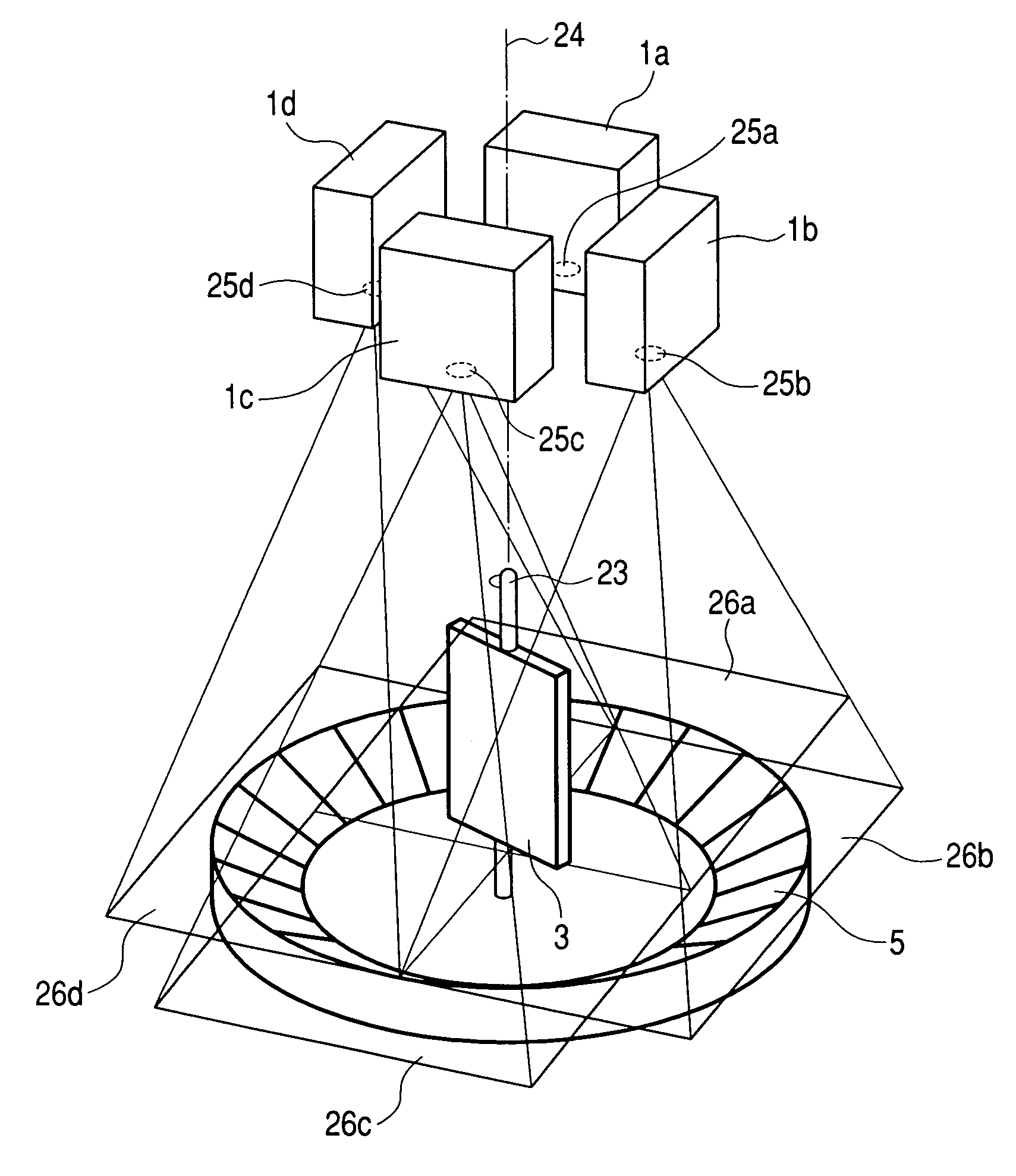
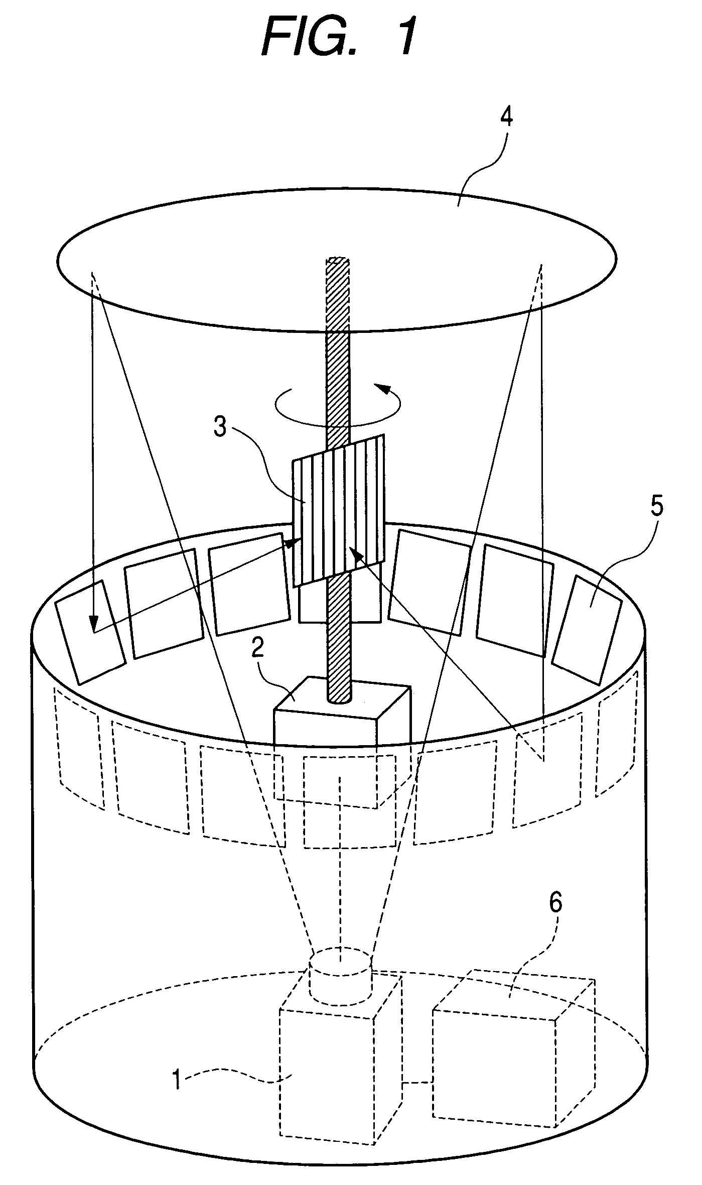
[0064]FIG. 1 is a perspective view of a display apparatus according to the present invention. Reference numeral 1 is an electronic projector, 2 is a rotary mechanism (rotary drive source), 3 is a view-angle-limiting filter-attached screen, 4 is a mirror, 5 is a polyhedral mirror (mirror group), and 6 is a control unit.

[0065]With reference to this figure, the view-angle-limiting filter-attached screen 3 is rotated continuously or stepwise by the rotary mechanism 2. The polyhedral mirror 5 is a mirror group comprising of a plurality of mirrors arrayed on the surface of a circular cone forming a circular conical surface and in a ring form on the locus of a circle of a radius centered on the central axis of the circular cone, and the mirror 4 is attached to the inner side (under side) of the ceiling of the display apparatus. These polyhedral mirror 5 and mirror 4 form a projection optical system. The electronic projector 1 such as a liquid crystal projector, projects images of an object...

second embodiment

[0086]Here, for the communication path 18, either cable or radio communication is possible. It is also possible to send acquired projection images to a remote display apparatus via a network. In this case, the image signals may be sent in a digital image format such as MPEG. Now, with this second embodiment of the display apparatus, a three-dimensional image of the object 15 can be viewed at a remote place.

[0087]Further, the principle of this image-pickup apparatus as shown in FIG. 11 allows its size to be adapted to the size of the image-pickup object. That is, the image-pickup apparatus can be optimized to the image-pickup object by designing the size of each face of the circular conical polyhedral mirror and the diameter of the mirror circle according to the size of the image-pickup object. As for the setup position of the CCD camera also, its height is adjusted so that the whole circular conical polyhedral mirror be within the vision of the camera and the image divisions from al...

fourth embodiment

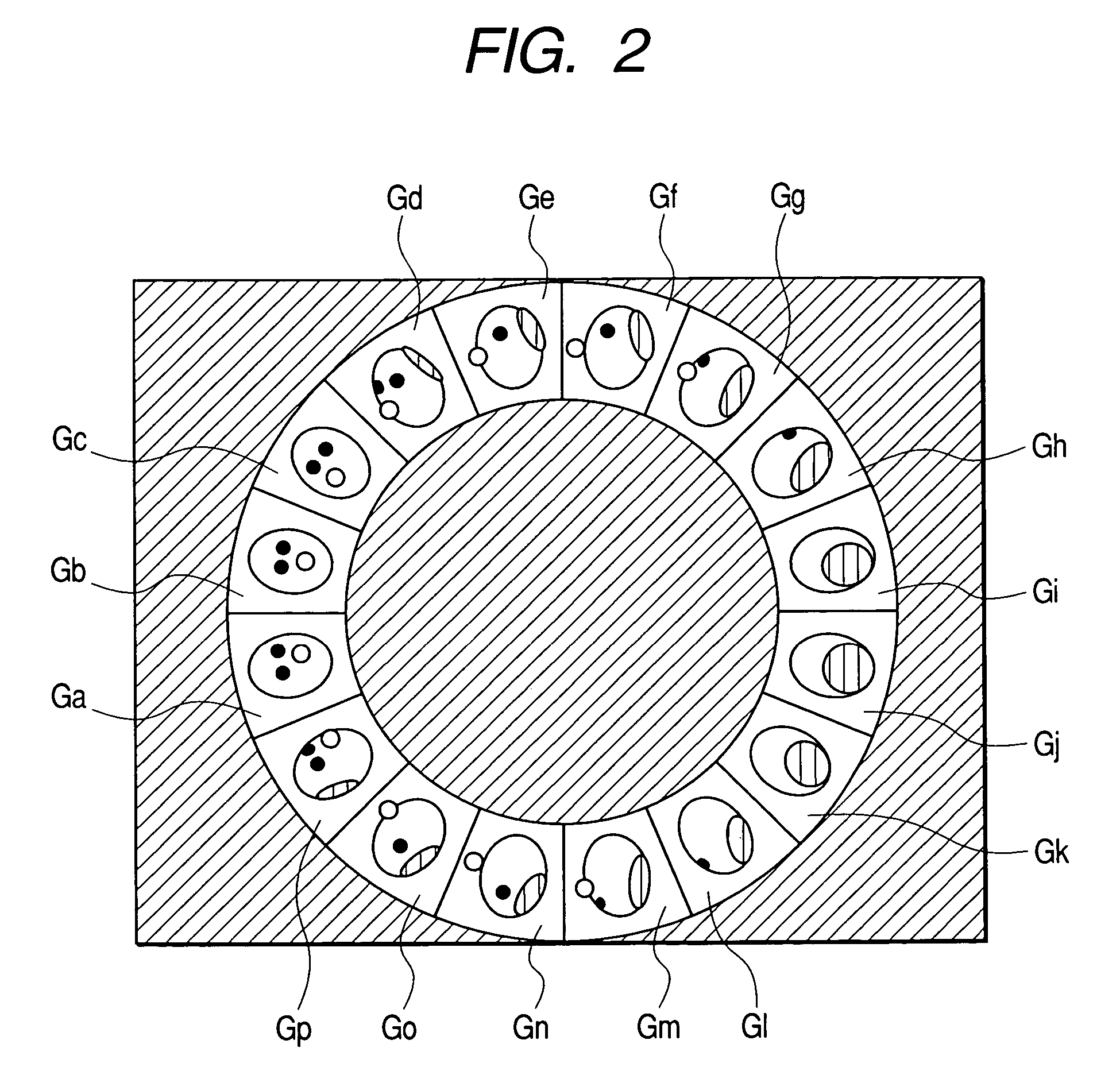
[0092]FIG. 17 is a longitudinal sectional view of the display apparatus according to the present invention. In this figure, a electron projector 1 projects a projection image as shown in FIG. 16 sent from a controlling unit 6. A mirror 4 attached to the inner side of the ceiling reflects this projected image, and then each image division Ga to Gi of the projected image is reflected by each mirror of polyhedral mirror 5, to be projected to the view-angle-limiting filter-attached screen 3.

[0093]The projection image projected from the electronic projector 1, as shown in FIG. 16, is an image of the image divisions Gb to Gi (those shown in FIG. 5) that are divided images of an object as viewed from different directions around the object arranged semi-circularly in a ring area. The images in FIG. 16 may be either created freely by computer graphics or the like or produced by a CCD camera as described with reference to FIG. 11.

[0094]In this configuration of a display apparatus according to...


PUM


Abstract

A display apparatus comprises a screen which can rotate and provides a part for controlling view angle, a mirror group which comprises a plurality of mirrors arrayed in a ring form along a surface of a circular cone which sets a central axis as an axis of rotation of the screen, and a plurality of electronic projectors arranged at positions where oppose to mirror faces of the mirrors comprising the mirror group and project different image divisions representing different sides of an object to the different mirror faces, wherein each of the electronic projectors is arranged so as to project the image division to the mirror group, and each of the mirrors is arranged on optical path of optical system which the image division projected from the electronic projector is reflected on the mirror face and is projected to the screen.

Description

CROSS REFERENCE TO RELATED APPLICATION[0001]This application is a Continuation-in-Part application of U.S. application Ser. No. 10 / 785,051 filed on Feb. 25, 2004. Priority is claimed based on the parent U.S. application Ser. No. 10 / 785,051 filed on Feb. 25, 2004, which claims priority to Japanese Patent Application Nos. 2003-073371 and 2004-028798 filed on Mar. 18, 2003 and Feb. 5, 2004, respectively. Priority is also claimed on Japanese Patent Application No. 2004-185173 filed on Jun. 23, 2004.BACKGROUND OF THE INVENTION[0002]The present invention relates to a display apparatus and an image-pickup apparatus which enable a person to see different sides of a displayed object by viewing a displayed image while moving around it, and provide an image viewable as a three-dimensional image of the object.[0003]A display apparatus has been proposed that displays three-dimensional images by using a rotary screen. In an example, this display apparatus produces a plurality of two-dimensional i...

Claims


Application Information

Patent Timeline
Patent Type & Authority Patents(United States)
IPC IPC(8): G03B21/26G03B21/28G03B21/56G03B21/60G09G5/00H04N9/31H04N13/307
CPCG03B21/14G03B21/28G03B35/24G03B37/04H04N13/0493H04N13/0207H04N13/0217H04N13/0402H04N13/0406G09F19/14G03B21/60H04N13/302H04N13/393H04N13/207H04N13/218H04N13/307
Inventor HOSHINO, TAKESHIOTSUKA, RIEKOISHIBASHI, ATSUSHIHORII, YOUICHIYANAGIMOTO, MANABUMARUYAMA, YUKINOBU
Owner HITACHI LTD
Why Eureka
Try Eureka