LED bulb

a technology of led bulbs and filaments, applied in the field of light sources, can solve the problems of increasing installation costs, short life of bulbs, and constant vibration of thin filaments,

Active Publication Date: 2006-06-13
OSRAM SYLVANIA INC
View PDF6 Cites 63 Cited by
  • Summary
  • Abstract
  • Description
  • Claims
  • Application Information

AI Technical Summary

Benefits of technology

[0008]This LED light source is completely self-contained and is capable of assembly to an existing reflector. The necessary electrical connection is supplied by a standard plug and socket arrangement, such as has been used for many years in the automotive field, thus eliminating the need for hard-wiring and custom circuitry.

Problems solved by technology

While working well and being inexpensive, these bulbs have a relatively short life and, of course, the thin filament employed was always subject to breakage due to vibration.
However, these LED sources have been hard-wired into their appropriate location, which increase the cost of installation.

Method used


Image

  • LED bulb
  • LED bulb
  • LED bulb

Examples


Embodiment Construction

[0014]For a better understanding of the present invention, together with other and further objects, advantages and capabilities thereof, reference is made to the following disclosure and appended claims taken in conjunction with the above-described drawings.

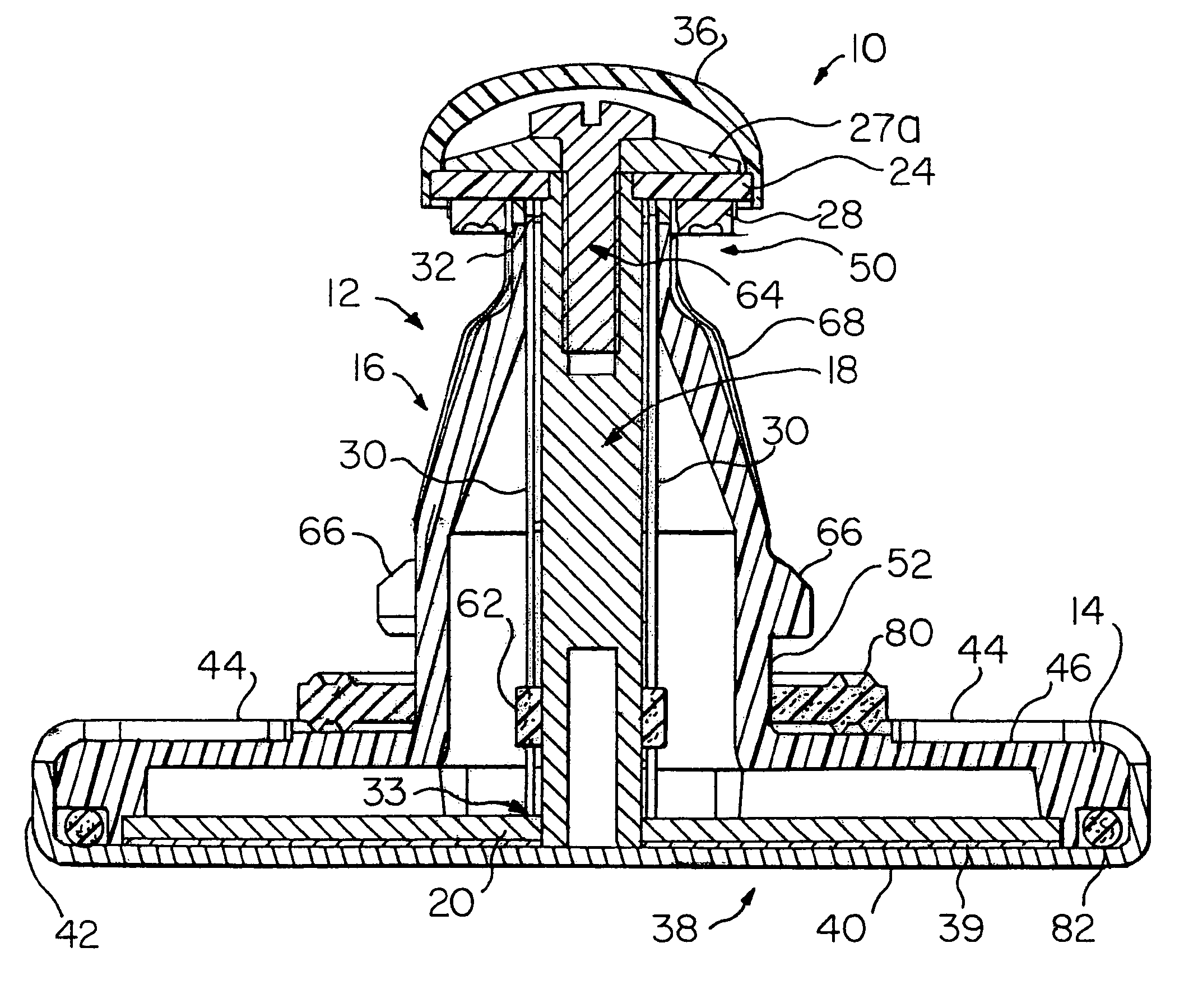
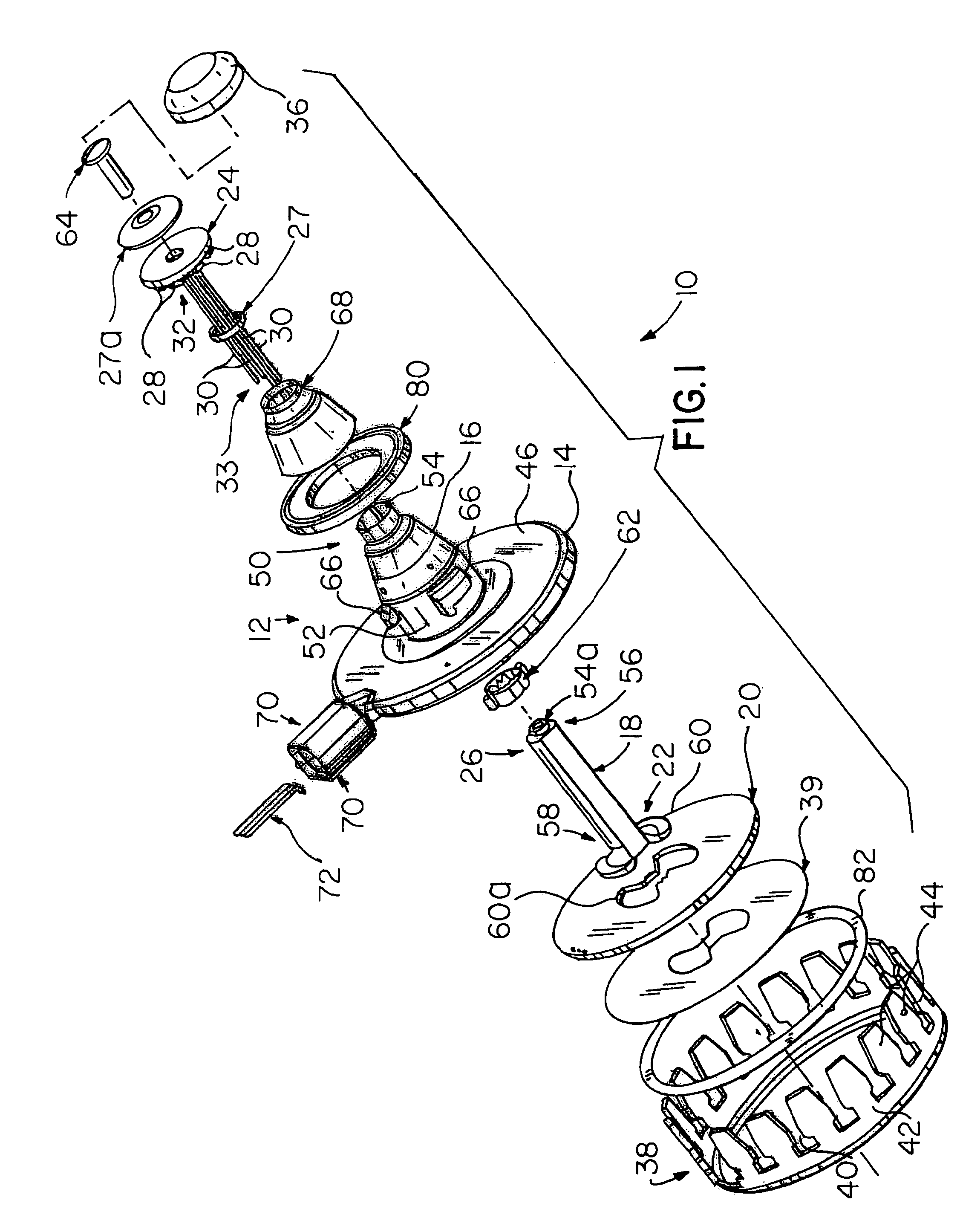
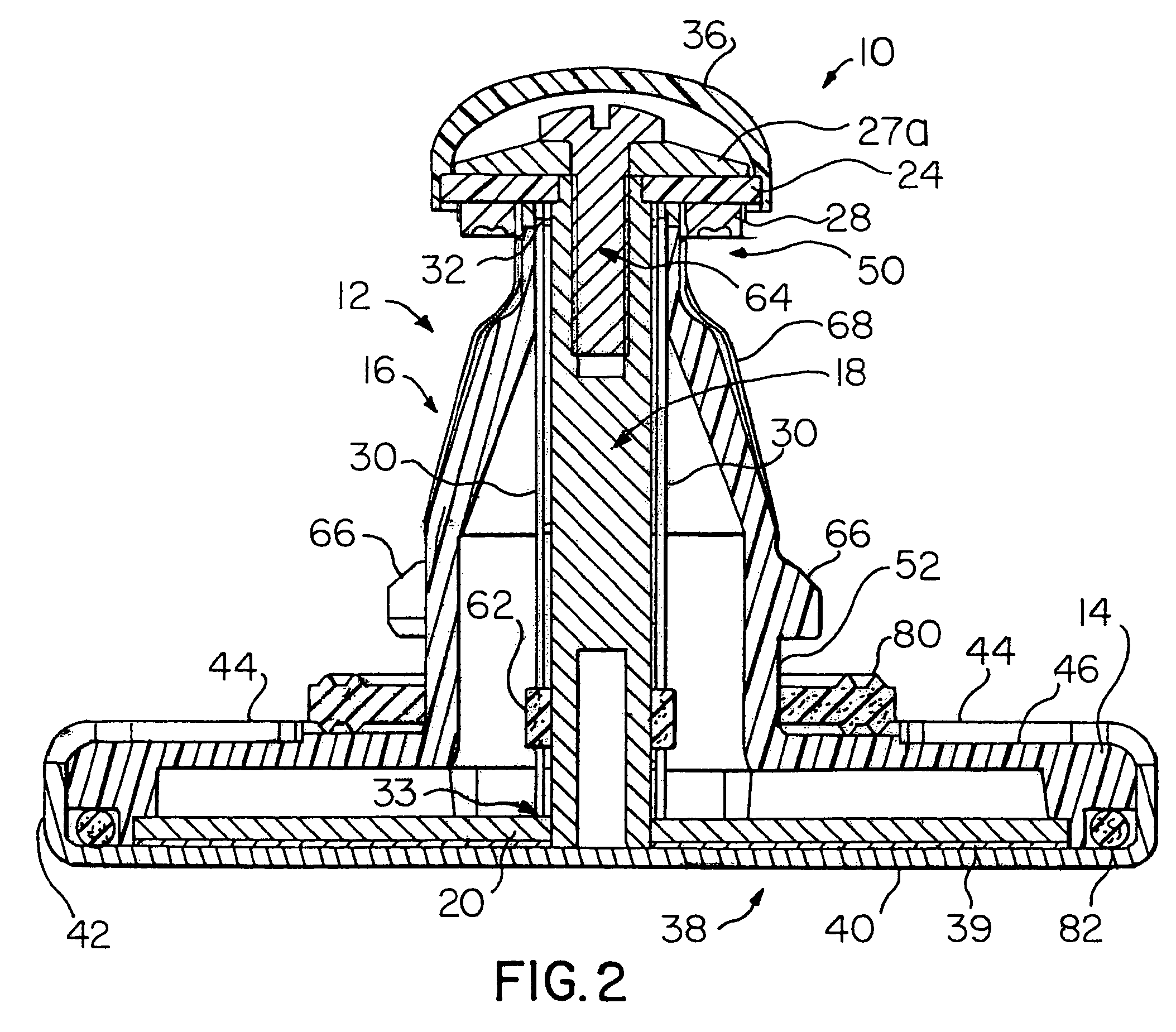
[0015]Referring now to the drawings with greater particularity, there is shown in FIG. 1 LED light source 10 comprising a housing 12 having a base 14. A hollow core 16 projects from the base, the core being substantially conical. A central heat conductor 18 is centrally located within the hollow core 16 and is formed of a suitable heat-conducting material, such as copper. Preferably, the central heat conductor 18 is press-fitted into the core. A first printed circuit board 20 is positioned in the base 14 and a second printed circuit board 24 is fitted to a second end 26 of the central heat conductor 18. The printed circuit board 20 is spaced from the post 18 so that the heat generated at printed circuit board 24 is conducted thro...


PUM


Abstract

An LED light source (10) has a housing (12) with a base (14). A central heat conductor (18) is centrally located within the hollow core (16) and is formed of a suitable heat-conducting material, such as copper. A cap (36) is fitted over a second printed circuit board (24), and a heat sink (38) is attached to the base (14) and in thermal contact with a first printed circuit board (20). The heat sink (38) has a bottom (40) with an upstanding side wall (42) terminating in a plurality of fingers (44), the fingers (44) being formed to overlie an upper surface (46) of the base (14). The heat sink (38) is preferably formed from black-anodized aluminum.

Description

TECHNICAL FIELD[0001]This invention relates to light sources and more particularly to light sources employing light emitting diodes (LED or LEDs) and more particularly to light sources useful in the automotive field such as for headlights, taillights, stoplights, fog lights, turn signals, etc. Still more particularly, it relates to such light sources packaged to achieve industry accepted interchangeability.BACKGROUND ART[0002]In the past, most automotive light sources have involved the use of incandescent bulbs. While working well and being inexpensive, these bulbs have a relatively short life and, of course, the thin filament employed was always subject to breakage due to vibration.[0003]Recently some of the uses, particularly the stoplight, have been replaced by LEDs. These solid-state light sources have incredible life times, in the area of 100,000 hours, and are not as subject to vibration failures. However, these LED sources have been hard-wired into their appropriate location,...

Claims


Application Information

Patent Timeline
Patent Type & Authority Patents(United States)
IPC IPC(8): F21V29/00F21S8/10F21K99/00F21Y101/02H01L33/64
CPCF21K9/00F21V29/83H01L33/642F21V29/74F21S48/115F21S48/215F21Y2101/02F21Y2115/10F21S43/14F21S41/153E03C1/26E03C1/264B02C21/00B65F1/14G06Q50/10
Inventor COUSHAINE, CHARLES M.ALBRIGHT, KIMTESSNOW, THOMASMADHANI, VIPIN
Owner OSRAM SYLVANIA INC
Why Eureka
Try Eureka