
Implant consisting of bone material

a technology of bone material and bone, applied in bone implants, tissue regeneration, medical science, etc., can solve the problems of nerve roots in this region and/or the spinal cord, metal implants breakage, and sharp edges of titanium baskets can damage nerve roots

Inactive Publication Date: 2006-06-13
TUTOGEN MEDICAL INC
View PDF25 Cites 70 Cited by
  • Summary
  • Abstract
  • Description
  • Claims
  • Application Information

AI Technical Summary

Benefits of technology

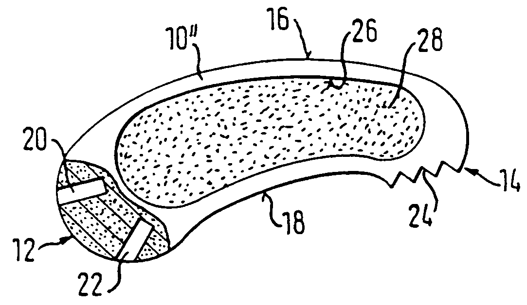
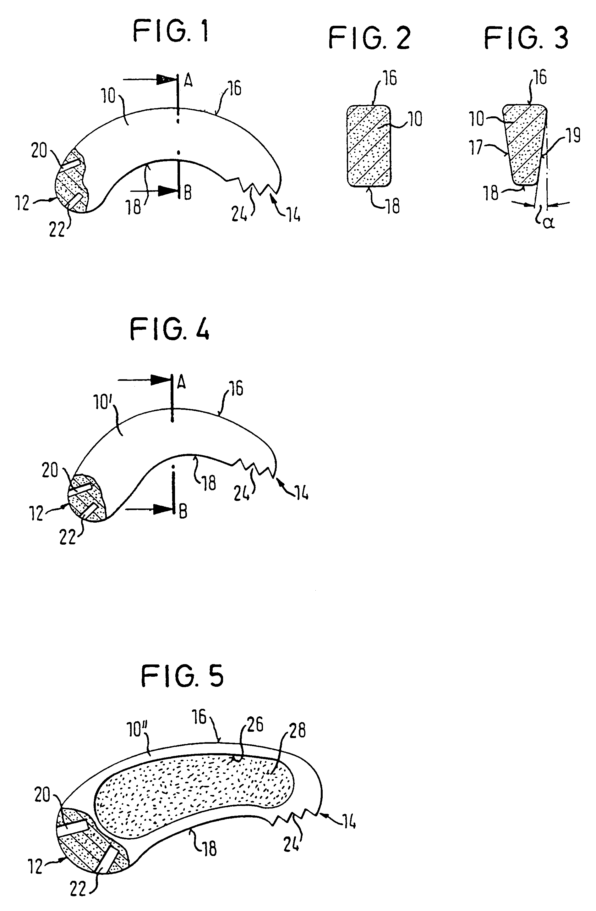
[0012]A special advantage of the spinal column implant in accordance with the invention is given by the material used which does not represent a foreign body due to its biological origin and to a special preservation. Furthermore, due to the curved design of the implant, the advantage results that it is matched to the shape of the front edge of the lumbar vertebrae and thus automatically comes into the right position on insertion.

Problems solved by technology

The result is a horizontal displaceability of the vertebral bodies relative to one another (spondylolisthesis), which leads to impairments of the nerve roots in this region and / or of the spinal cord together with the pain resulting from this.
These implants are subject in particular in the lumbar vertebral column to considerable forces, which can lead to the breakage of the metal implant.
On the one hand, the sharp edges of the titanium baskets can damage the nerve roots during introduction.
Furthermore, no lordosiation is possible as the baskets are practically introduced blind.
The titanium makes the fusion control more difficult due to artifacts and in computer tomography.
Furthermore, the implant removal in revision operations is extremely difficult.

Method used


Image

  • Implant consisting of bone material
  • Implant consisting of bone material

Examples


Embodiment Construction

[0014]The present invention will be described in the following in a purely exemplary manner with reference to embodiments of a spinal column implant in accordance with the invention and with reference to the accompanying drawings. There are shown:

[0015]FIG. 1 is a plan view of an embodiment of a spinal column implant in accordance with the present invention;

[0016]FIGS. 2 and 3 are in each case possible cross-sectional shapes of the spinal column implants in accordance with the invention;

[0017]FIG. 4 is a plan view of a further embodiment of a spinal column implant in accordance with the present invention; and

[0018]FIG. 5 is a plan view of a further embodiment of a spinal column implant in accordance with the present invention.

DETAILED DESCRIPTION OF THE INVENTION

[0019]In accordance with the invention, the body can consist of processed, preserved and sterile bone material of human origin, a so-called allograft, or of processed, preserved and sterile bone material of animal origin, a ...


PUM

PropertyMeasurementUnit
angleaaaaaaaaaa
depthaaaaaaaaaa
pHaaaaaaaaaa

Abstract

The invention relates to a vertebral column implant for intercorporal fusion on the vertebral column, consisting of a body which consists of bone material and which is curved in the direction in which it extends longitudinally. The size of the implant is adapted to the intermediate vertebral space available between adjacent vertebrae after the intermediate vertebral body has been removed.

Description

CROSS-REFERENCE TO RELATED APPLICATIONS[0001]This application is the U.S. National Phase of PCT / EP00 / 10672 filed Oct. 30, 2002, which in turn claims priority of German Patent Application DE 199 52 939.6 filed Nov. 3, 1999, the contents of which are incorporated herein by reference.FIELD OF THE INVENTION[0002]The present invention relates to an implant for the connection of bones and in particular to a spinal column implant for the intercorporal fusion of vertebrae which is inserted between two vertebrae to be fused.BACKGROUND OF THE INVENTION[0003]Through the degeneration of the vertebral disc, in particular of the vertebral disc nucleus (nucleus pulposus) a loss of height in the affected vertebral disc space often comes about which is connected with a loosening of the vertebral disc annulus (annulus fibrosus) and of the ligaments. Through this, the spinal column becomes instable at this location. The result is a horizontal displaceability of the vertebral bodies relative to one ano...

Claims


Application Information

Patent Timeline
Patent Type & Authority Patents(United States)
IPC IPC(8): A61F2/44A61F2/00A61F2/28A61F2/30A61F2/46A61L27/36
CPCA61F2/4455A61L27/3608A61L27/3658A61F2/28A61F2310/00359A61F2/4611A61F2002/2835A61F2002/30112A61F2002/30131A61F2002/30153A61F2002/30158A61F2002/30324A61F2002/30779A61F2002/3081A61F2002/30904A61F2002/4475A61F2230/0004A61F2230/0013A61F2230/0019A61F2230/0026A61F2250/0036A61L2430/38A61F2/442A61F2002/30593
Inventor SCHOPF, CHRISTOPHKOSCHATZKY, KARLKALAS, ROLF-DIETERLOWEL, MATTHIAS
Owner TUTOGEN MEDICAL INC
Learn More