Method and apparatus for implant stability

a technology of implant stability and apparatus, applied in the field of method and apparatus for implant stability, can solve the problems of narrow disc space, annular ligament bulging, and inability so as to achieve implant stability, improve implant stability, and increase the stability within the intervertebral space

Inactive Publication Date: 2006-06-13
DEPUY SPINE INC (US)
View PDF10 Cites 305 Cited by
  • Summary
  • Abstract
  • Description
  • Claims
  • Application Information

AI Technical Summary

Benefits of technology

[0009]The invention is generally related to a method and apparatus for improving implant stability within an intervertebral space. As such, there is provided a method of achieving stability of an implant in the intervertebral space of the human body including, preparing the intervertebral space for implantation, positioning an implant in th

Problems solved by technology

This would be impossible if each spinal segment were locked into a single axis of motion.
An unhealthy disc may result in pain.
This results in a narrowing of the disc space and a bulging of the annular ligaments.
With progressive nuclear dehydration, the annular fibers can crack and tear.
Further, loss of normal soft tissue tension may allow for a partial dislocation of the joint, leading to bone spurs, foraminal narrowing, mechanical instability, and pain.
First, if the annular fibers stretch or rupture, the nuclear material may bulge or herniate and compress neural tissues resulting in leg pain and weakness.
This condition will typically

Method used


Image

  • Method and apparatus for implant stability
  • Method and apparatus for implant stability
  • Method and apparatus for implant stability

Examples


Embodiment Construction

[0038]The foregoing and other objects, features and advantages of the invention will be apparent from the following more particular description of preferred embodiments of the invention, as illustrated in the accompanying drawings in which like reference characters refer to the same parts throughout the different views. The same number appearing in different drawings represent the same item. The drawings are not necessarily to scale, emphasis instead being placed upon illustrating the principles of the invention.

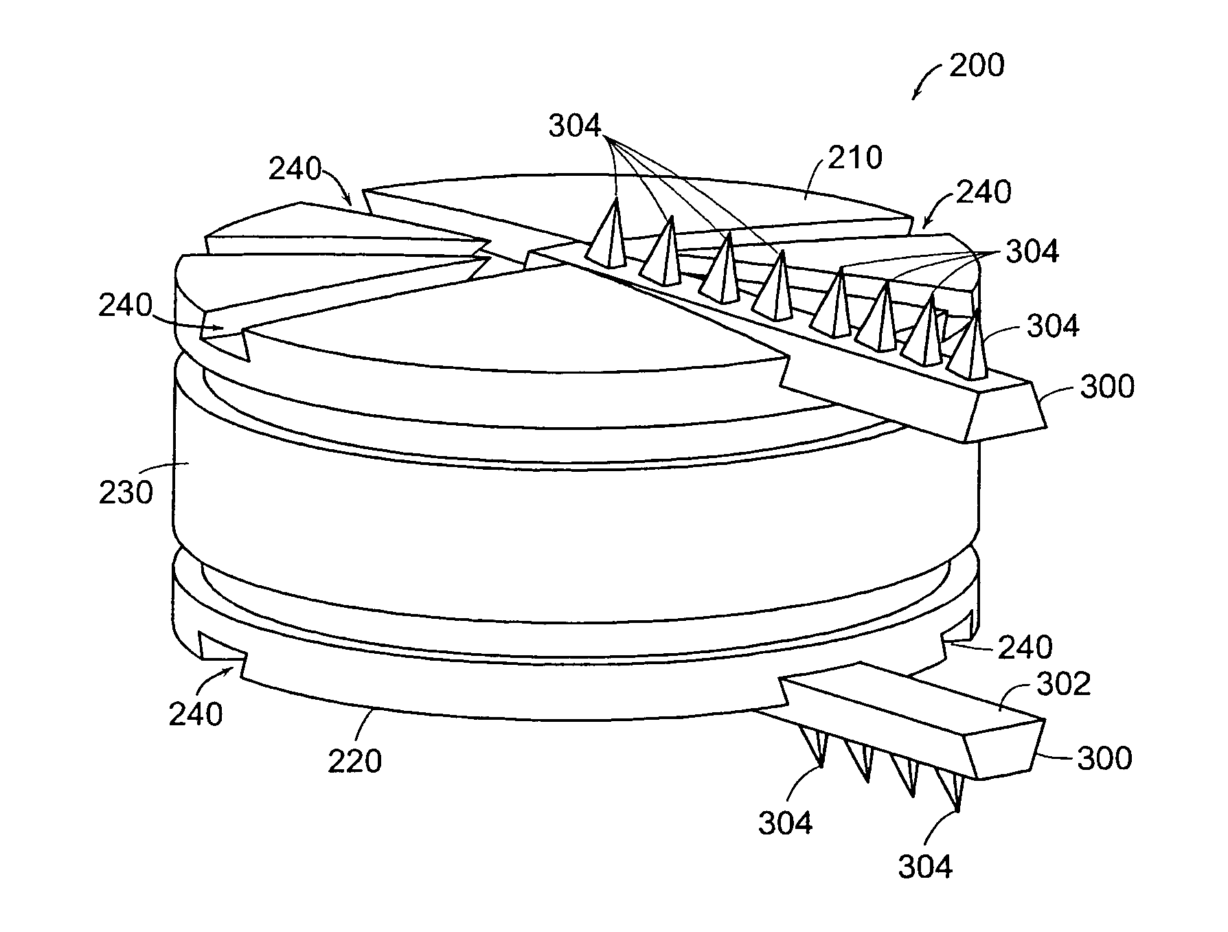
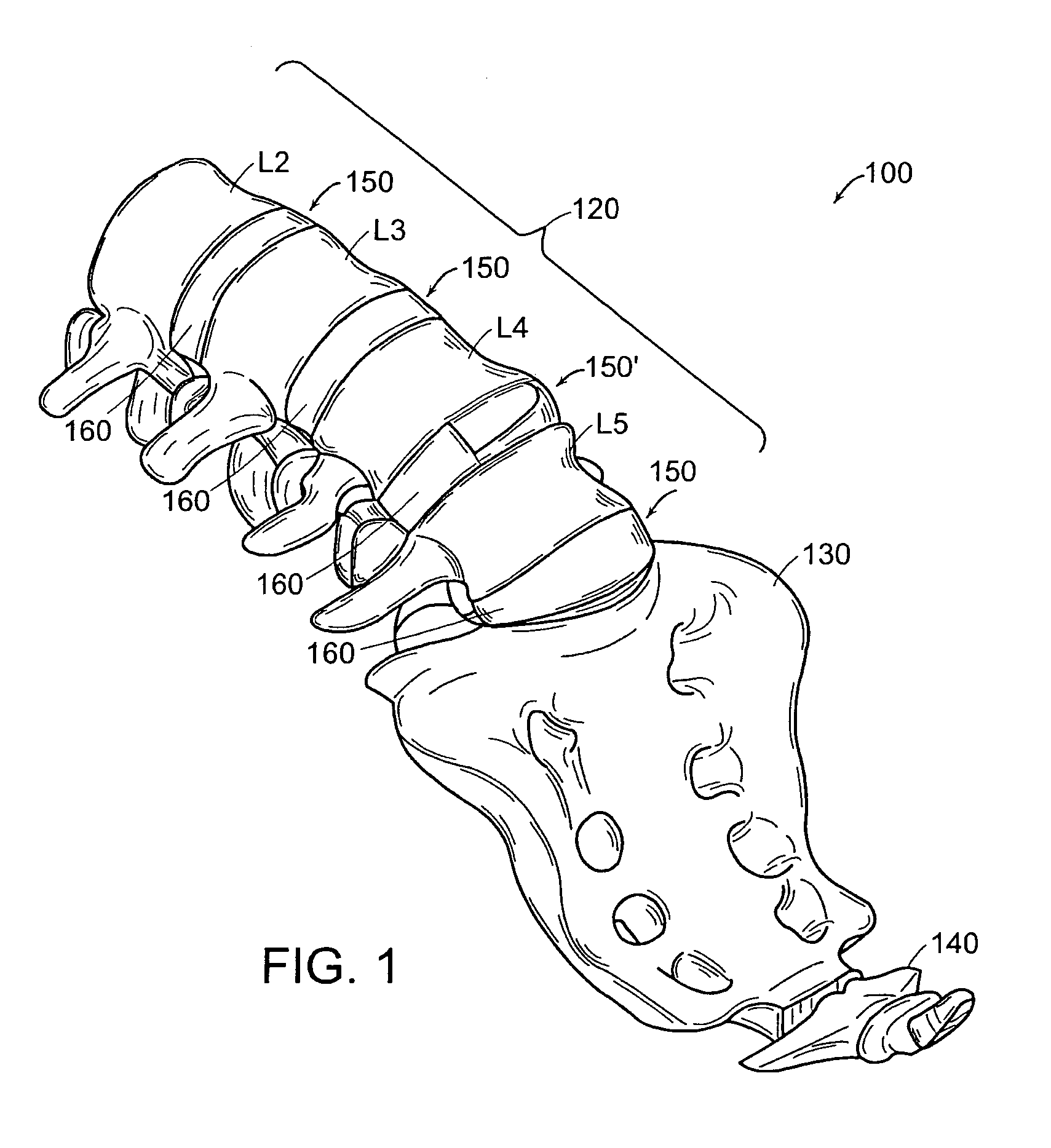
[0039]In general, the surgical procedure for implantation utilizes an anterior approach. During the surgery, a small incision is made in the abdomen below the belly button. The organs are carefully moved to the side so the surgeon can visualize the spine. The surgeon then removes a portion of a damaged disc. The implant is inserted into the into the intervertebral space. The implant stays in place from the tension in spinal ligaments and the remaining part of the annulus of ...


PUM


Abstract

An method and apparatus is provided for achieving stability of an implant in an intervertebral space of the human body, including an implant having a superior surface and an inferior surface, the surfaces having no significant protrusions extending therefrom and at least one modular projection mateable with one of each superior and inferior surface of the implant to achieve stability within the intervertebral space. The implants can be selected form a group of artificial discs and spinal fusion cages.

Description

BACKGROUND OF THE INVENTION[0001]An intervertebral disc has several important functions, including functioning as a spacer, a shock absorber, and a motion unit.[0002]The disc maintains the separation distance between adjacent boney vertebral bodies. The separation distance allows motion to occur, with the cumulative effect of each spinal segment yielding the total range of motion of the spine in several directions. Proper spacing is important because it allows the intervertebral foramen to maintain its height, which allows the segmental nerve roots room to exit each spinal level without compression.[0003]Further, the disc allows the spine to compress and rebound when the spine is axially loaded during such activities as jumping and running. Importantly, it also resists the downward pull of gravity on the head and trunk during prolonged sitting and standing.[0004]Furthermore, the disc allows the spinal segment to flex, rotate, and bend to the side, all at the same time during a parti...

Claims


Application Information

Patent Timeline
IPC IPC(8): A61F2/44A61B17/00A61B17/02A61F2/00A61F2/30A61F2/46
CPCA61F2/442A61F2/4611A61B17/025A61B17/00234A61F2220/0025A61B2017/0256A61F2002/30387A61F2002/30563A61F2002/30579A61F2002/30604A61F2002/30823A61F2002/30841A61F2002/30848A61F2002/30884A61F2002/4627A61F2002/4628A61F2002/4635A61F2002/30845
Inventor FRASER, ROBERTHAWKINS, JOHN RILEYROGERS, CHRISTOPHERDOORIS, ANDREWLIONETTO, MARK
Owner DEPUY SPINE INC (US)
Why Eureka
Try Eureka