Spine treatment devices and methods

a technology for spine disorders and devices, applied in the field of spine implants, can solve the problems of high surgical risk, uncertain outcome and efficacy of spine implants, and high risk of fusion procedures, so as to reduce nerve compression, increase intervertebral spacing, and increase the volume of spinal canals

Inactive Publication Date: 2008-08-28
DFINE INC
View PDF50 Cites 57 Cited by
  • Summary
  • Abstract
  • Description
  • Claims
  • Application Information

AI Technical Summary

Benefits of technology

[0017]Other implant systems and methods within the spirit and scope of the invention can be used to increase intervertebral spacing, increase the volume of the spinal canal and off-load the facet joints to thereby reduce compression on nerves and vessels to alleviate pain associated therewith.

Problems solved by technology

Many surgical and non-surgical treatments exist for patients with degenerative disc disease (DDD), but often the outcome and efficacy of these treatments are uncertain.
Fusion procedures are highly invasive procedures that carry surgical risk as well as the risk of transition syndrome, wherein adjacent levels of the vertebrae will be at increased risk for facet and discogenic pain.
While there have been significant advances in spinal fusion devices and surgical techniques, the procedure does not always work reliably.
Probably the most significant drawback of spinal fusion is termed the “transition syndrome” which describes the premature degeneration of discs at adjacent levels of the spine.
This is certainly the most vexing problem facing relatively young patients when considering spinal fusion surgery.
Repetitive or excessive trunkal motions, especially in rotation or extension, can irritate and injure facet joints or their encasing fibers.
Also, abnormal spinal biomechanics and bad posture can significantly increase stresses and thus accelerate wear and tear on the facet joints.
However, such disc replacement procedures are still highly invasive procedures which require an anterior surgical approach through the abdomen.
Any disruption of the components that stabilize a vertebral segment (i.e., discs, facets, ligaments) decrease the clinical stability of the spine.

Method used


Image

  • Spine treatment devices and methods
  • Spine treatment devices and methods
  • Spine treatment devices and methods

Examples


Embodiment Construction

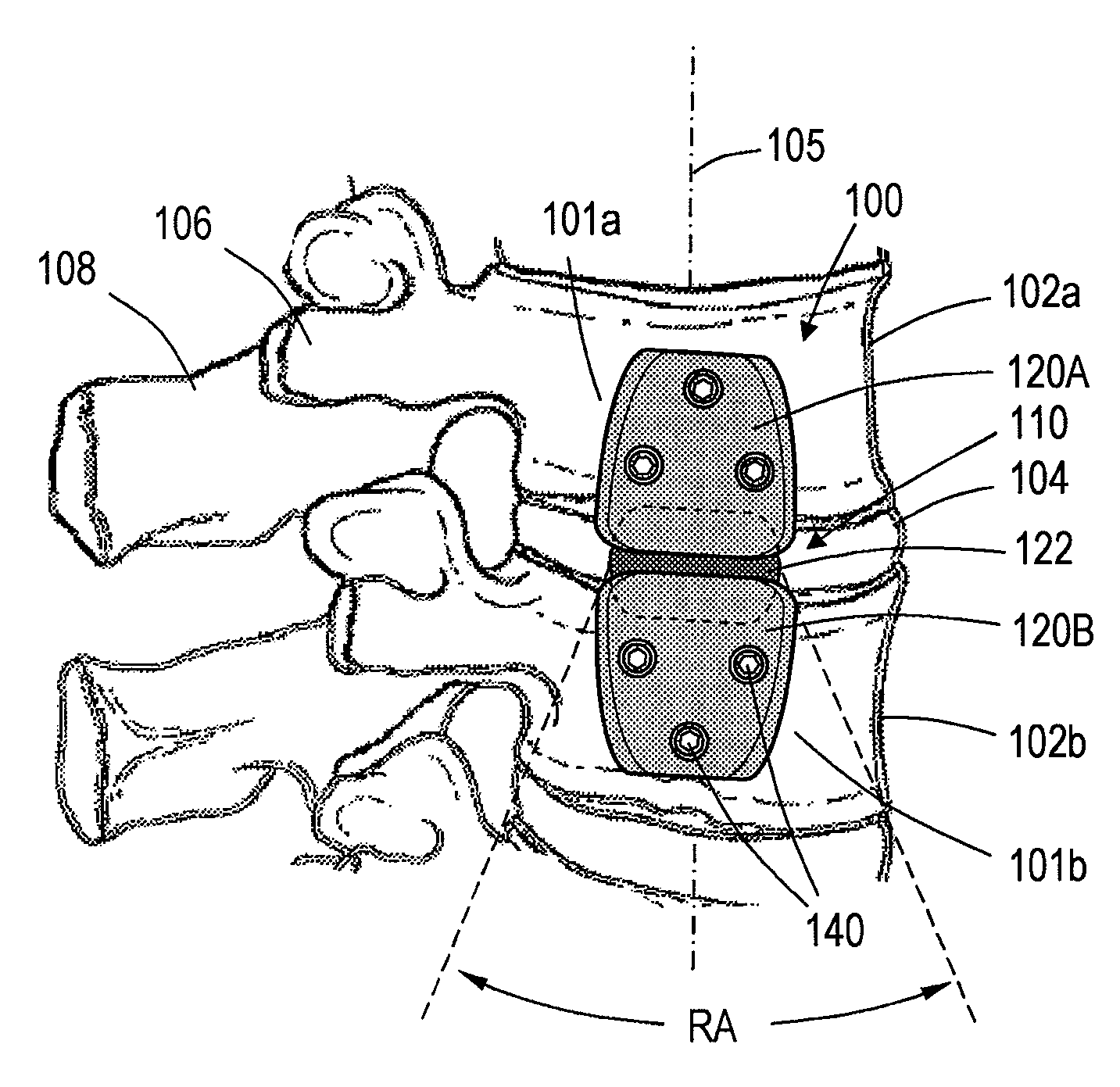
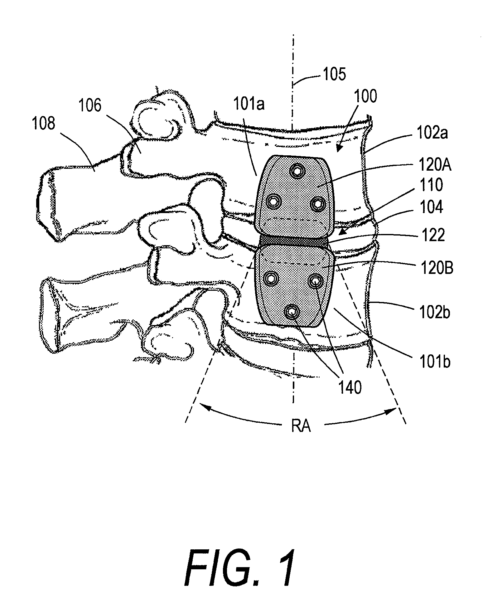
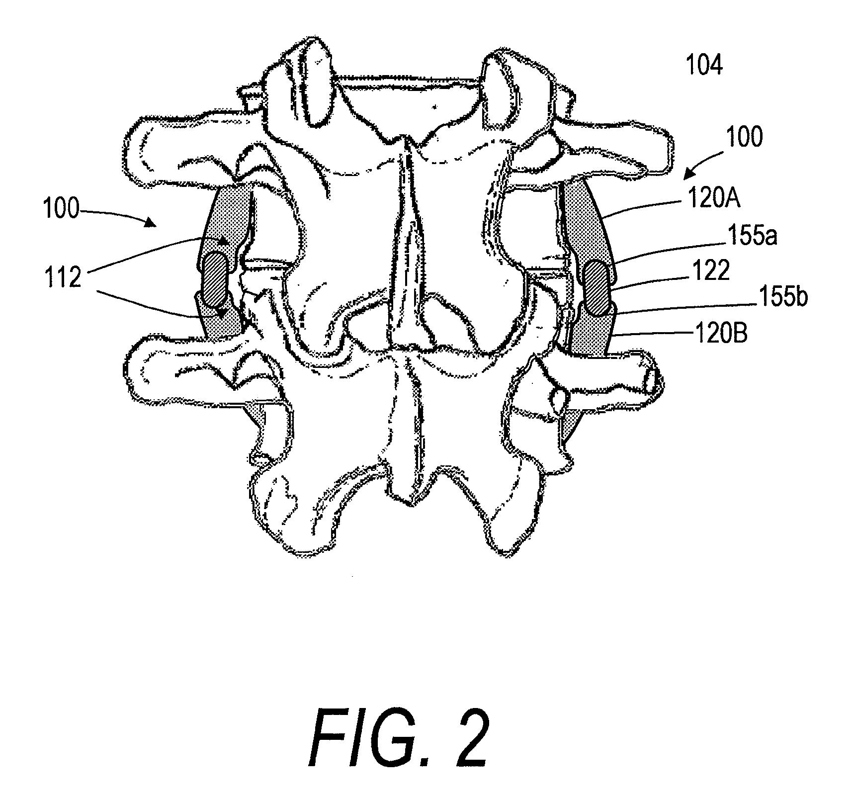
[0028]FIGS. 1-3 show a spine segment and one embodiment of a spine implant system, the implant system having an implant body or assembly 100 extending between outward or lateral surfaces 101a and 101b of first and second vertebra 102a and 102b. It can be seen that the intermediate portion 110 of the implant body 100 spans disc 104, with the implant body generally extending in a superior-inferior direction in alignment with axis 105 of the spine segment. The implant body 100 can extend between lateral or outward surfaces of the anterior vertebra, as opposed to the pedicles 106 or spinous processes 108. In a preferred embodiment the first and second vertebrae 102a and 102b can be lumbar or thoracic vertebrae. In another embodiment the first and second vertebra 102a and 102b can be cervical vertebrae.

[0029]Still referring to FIGS. 1 and 2, each implant body 100 can have a first (e.g., superior) body portion 120A and a second (e.g., inferior) body portion 120B. In some embodiments, as i...


PUM


Abstract

A modular implant system and method is provided for the dynamic stabilization of a spine segment and that can be implanted in a posterior approach. The implant system can include first and second support bodies configured for fixation to outward or lateral surfaces of first and second vertebrae, respectively. The implant system can also comprise a resilient portion. The method can comprise fixating first and second support bodies to first and second vertebrae respectively.

Description

CROSS-REFERENCE TO RELATED APPLICATIONS[0001]This application claims the benefit of U.S. Provisional Application No. 60 / 902,492 filed Feb. 22, 2007, the entire contents of which are hereby incorporated by reference and should be considered a part of this specification. This application is also related to U.S. application Ser. No. 11 / 165,652, filed Jun. 24, 2005 which claims the benefit of Provisional U.S. Patent Application No. 60 / 633,509, filed Dec. 6, 2004. This application is also related to U.S. patent application Ser. No. 11 / 165,651, filed Jun. 24, 2005. The entire contents of all of the above applications are hereby incorporated by reference and should be considered a part of this specification.BACKGROUND OF THE INVENTION[0002]1. Field of the Invention[0003]The present invention relates generally to implant systems and methods for treating a spine disorder, and more particularly relates to braces and support members that can be configured for re-distributing loads within a spi...

Claims


Application Information

Patent Timeline
Patent Type & Authority Applications(United States)
IPC IPC(8): A61B17/58A61F2/44
CPCA61B17/1642A61B17/7059A61B2017/00867A61B17/8085A61B2017/00557A61B17/7098
Inventor TRUCKAI, CSABASHADDUCK, JOHN H.
Owner DFINE INC
Why Eureka
Try Eureka