Inline power device detection

a detection device and power supply technology, applied in pulse generators, pulse techniques, pulse train generators, etc., can solve the problems of ethernet inline power destroying the termination resistor of the bob smith termination, communication devices may be damaged, etc., and achieve the effect of reducing the probability of damage to communications devices not configured to receive inline power

Active Publication Date: 2006-06-13
CISCO TECH INC
View PDF62 Cites 44 Cited by
  • Summary
  • Abstract
  • Description
  • Claims
  • Application Information

AI Technical Summary

Benefits of technology

[0005]Some embodiments of the invention provide numerous technical advantages. Some embodiments may benefit from some, none, or all of these advantages. For example, in one embodiment, communications devices may be plugged into an inline power jack for data communication regardless of whether the device is configured to receive inline power. In one embodiment, the probability of damage to communications devices that are not configured to receive inline power is reduced. In one embodiment, inline power is automatically turned on or off depending on the power configuration of the communications device.

Problems solved by technology

Such a communications device may be damaged when the device is plugged into a jack that provides inline power.
For example, ethernet inline power may destroy the bob smith termination resistors that are coupled to the center tap of isolation transformers in the communications device.

Method used


Image

  • Inline power device detection
  • Inline power device detection
  • Inline power device detection

Examples


Embodiment Construction

[0015]Embodiments of the invention are best understood by referring to FIGS. 1 through 4B of the drawings, like numerals being used for like and corresponding parts of the various drawings.

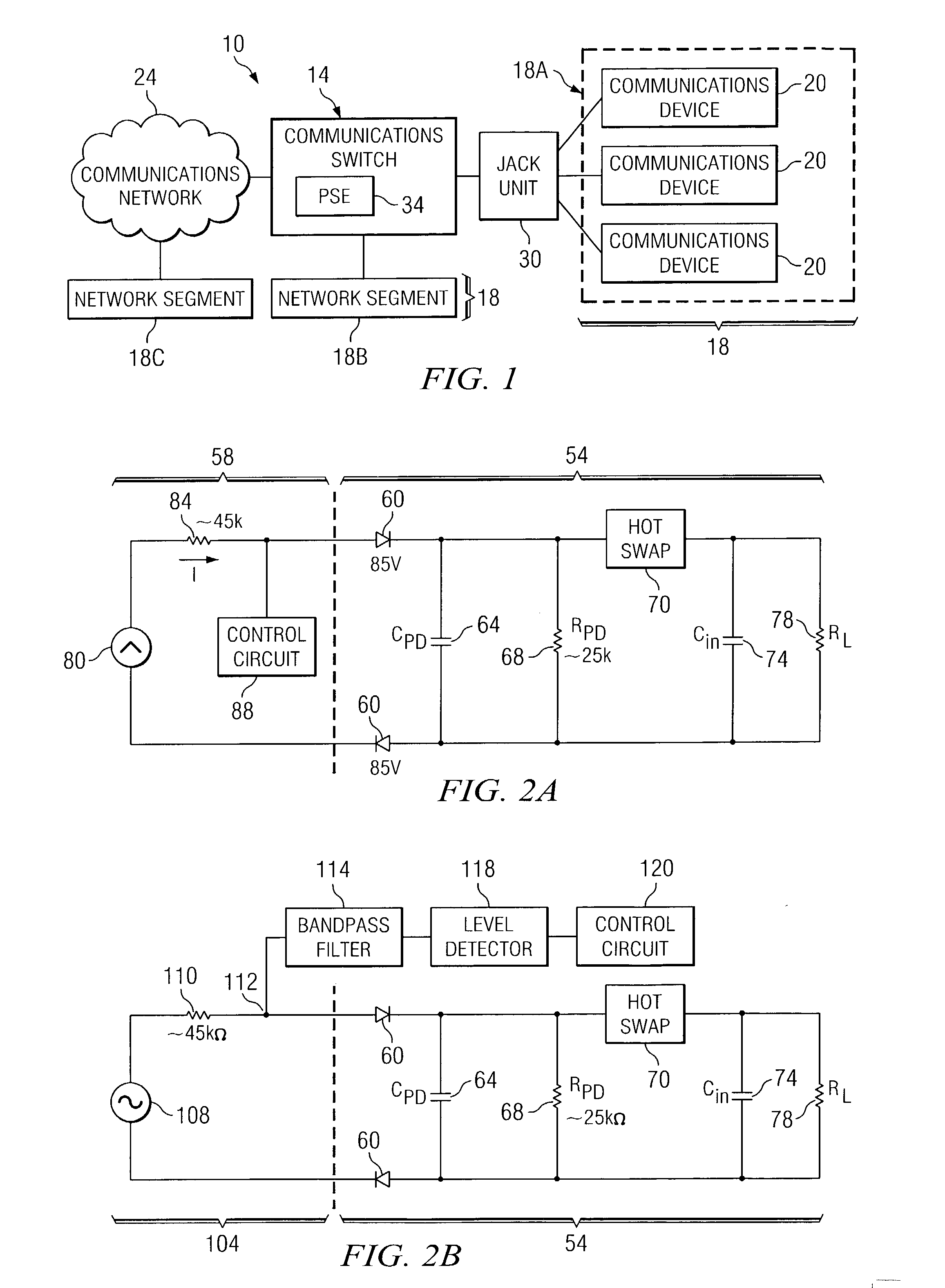
[0016]FIG. 1 is a schematic diagram illustrating one embodiment of a communications system 10 that may benefit from the teachings of the present invention. System 10 comprises network segments 18A through 18C that are coupled to each other over a communications network 24 and / or a communications switch 14. Network segments 18A through 18C are jointly referred to as network segments 18. As shown in FIG. 1, network segment 18A is coupled to network segment 18B over communications switch 14. Network segment 18C is coupled to network segments 18A and 18B over communications network 24 and communications switch 14. More or less network segments 18 may be coupled to each other over communications network 24 and communications switch 14.

[0017]Network segments 18A through 18C each comprise one or more com...


PUM


Abstract

According to one embodiment of the invention, a method for providing power to a device coupled to a communications switch through a data line is provided. The method includes determining that the device includes a diode. The method also includes providing power to the device in response to the determination.

Description

TECHNICAL FIELD OF THE INVENTION[0001]This invention relates generally to the field of electronic devices and more particularly to inline power device detection.BACKGROUND OF THE INVENTION[0002]A communications switch, such as an ethernet switch, allows a plurality of communications devices to communicate with each other. To establish a conduit for data between the communications switch and the communications device, a connector may be coupled to a printed circuit board (“PCB”) of the communications switch so that the communications device may plug into the connector to establish a data conduit. Such a connector is often referred to as a “jack.” Some communications switches also provide power through the jack, eliminating the need for the communications device to have a separate power source. Providing power through the jack is referred to as “inline power.”[0003]A communications device that is not configured to receive inline power relies on a separate AC or DC power source for pow...

Claims


Application Information

Patent Timeline
Patent Type & Authority Patents(United States)
IPC IPC(8): H03K3/00
CPCH04B3/46
Inventor MARSHALL, ROBERT A.
Owner CISCO TECH INC
Why Eureka
Try Eureka