Structure of inductance core and wire frame

a technology of inductance core and wire frame, which is applied in the direction of coils, transformers/inductance details, inductances, etc., can solve the problems of inductance leakage of inductance or transformer, hardly improve the magnetic-induction efficiency, etc., to improve the efficiency of inductance devices, reduce inductance leakage, and increase the covering area of the cor

Active Publication Date: 2006-06-13
YANG SEN TAI
View PDF3 Cites 73 Cited by
  • Summary
  • Abstract
  • Description
  • Claims
  • Application Information

AI Technical Summary

Benefits of technology

[0006]In light of the above-mentioned disadvantages of the prior arts, the invention provides an improved structure of inductance core and wire frame that can effectively increase the covering area of the core with respect to the coil, lessen the inductance leakage and improve the efficiency of inductance device. It aims to ameliorate at least some of the disadvantages of the prior art or to provide a useful alternative. The objective of the invention is to provide a center post at the center portion of the core. A containing circumferential channel is also provided at the periphery of the center post to make the outer circumference of the containing circumferential channel form a surrounded circumferential side wall that has small area of indentation openings at the end corners only. A center hole is also provided at the center portion of the wire frame that accommodates the center post, and a bobbin for the winding of the coil is further provided at the outer circumference of the center hole. A salient lead-out seat is provided at the end corner of the wire frame, and brazing posts are also provided on the same side at the upper edge of each of the lead-out seat to connect to the drawing head of the coil. By the use of the center post of the core embedding into the center hole of the wire frame, as well as making use of the containing circumferential channel to contain the wire frame, each of the lead-out seat of the wire frame can stretch out through the openings of the core. The magnetic leakage can be lessened and the inductance efficiency can be improved by making use of the circumferential side wall to form an integral surrounded covering. The accomplishment of this and other objectives of the invention will become apparent from the following description and its accompanying drawings of which:

Problems solved by technology

This will result in serious inductance leakage of the inductance or the transformer and will hardly improve the magnetic-induction efficiency.

Method used


Image

  • Structure of inductance core and wire frame
  • Structure of inductance core and wire frame
  • Structure of inductance core and wire frame

Examples


Embodiment Construction

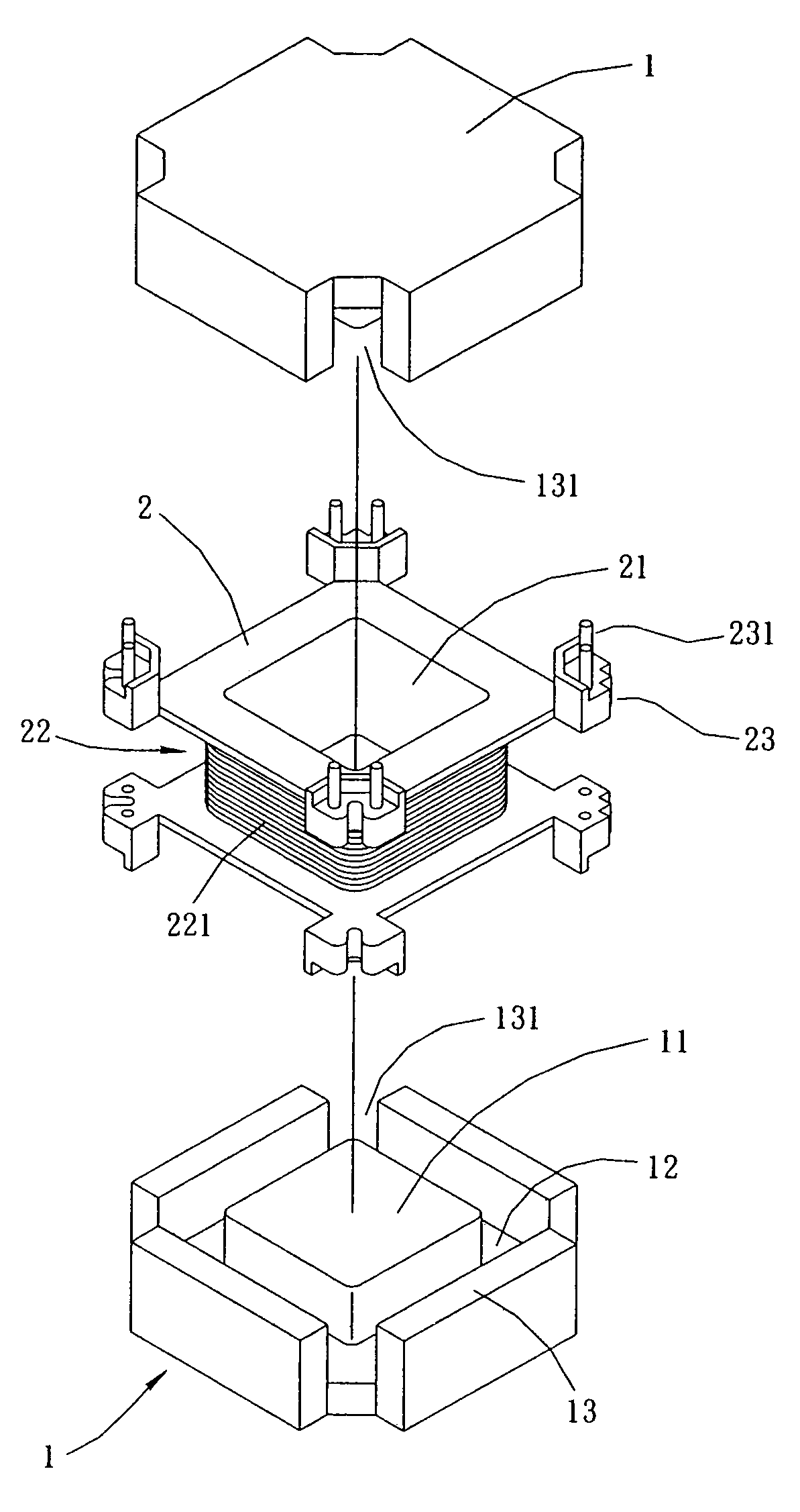
[0012]FIG. 4 is an exploded and isometric view of the inductance core and its relevant element structure of the invention. As shown in FIG. 4, the invention mainly includes two portions: a core (1) and a wire frame (2). A center post (11) equipping at the center portion of the core (1) has a containing circumferential channel (12) providing at the periphery thereof and forming naturally a surrounded circumferential side wall (13) having small area of openings (131) at the corners. Moreover, a center hole (21) providing at the center portion of the wire frame (2) has a bobbin (22) providing at the periphery thereof for the winding of a coil (221). What is more, a salient lead-out seat (23) providing at the corners of the wire frame (2) has a brazing post (231) extending on the same side at each of the lead-out seat (23) and connecting respectively to the drawing head drawn from a coil (221).

[0013]FIG. 5 is an isometric view of the invention after being assembled. As shown in FIG. 5, ...


PUM

PropertyMeasurementUnit
inductanceaaaaaaaaaa
structureaaaaaaaaaa
areaaaaaaaaaaa

Abstract

An improved structure of inductance core and wire frame mainly provides a center post at the center portion of the core. A containing circumferential channel is also provided at the periphery of the center post to make the outer circumference of the containing circumferential channel form a surrounded circumferential side wall that has small area of indentation openings at the end corners only. A center hole is also provided at the center portion of the wire frame that accommodates the center post, and a bobbin for the winding of the coil is further provided at the outer circumference of the center hole. A salient lead-out seat is provided at the end corner of the wire frame, and brazing posts are also provided on the same side at the upper edge of each of the lead-out seat to connect to the drawing head of the coil. By the use of the center post of the core embedding into the center hole of the wire frame, as well as making use of the containing circumferential channel to contain the wire frame, each of the lead-out seat of the wire frame can stretch out through the openings of the core. The magnetic leakage can be lessened and the inductance efficiency can be improved by making use of the circumferential side wall to form an integral surrounded covering.

Description

BACKGROUND OF THE INVENTION[0001]1. Field of the Invention[0002]The invention relates to an improved structure of inductance core and wire frame, and more particularly, to a core structure that can effectively increase the covering area of the core with respect to the coil, lessen the inductance leakage and improve the efficiency of inductance device.[0003]2. Description of the Prior Art[0004]As shown in FIG. 1, the core (5) of a conventional core structure of the inductance or the transformer appears mainly in E-shape. The core (5) includes a center post (51) and two side posts (53) that are salient in the same direction and disposed at the center and at the ends thereof respectively, as well as recessed portions (52) positioned between the center post (51) and the side posts (53). A wire frame (6), being accommodating the core (5) for assembling into an inductance or a transformer, has a center hole (61) at the center portion thereof. The center hole (61) has a bobbin (62) at the ...

Claims


Application Information

Patent Timeline
Patent Type & Authority Patents(United States)
IPC IPC(8): H01F27/30
CPCH01F17/043H01F2005/046
Inventor YANG, SEN-TAI
Owner YANG SEN TAI
Why Eureka
Try Eureka