
Optical digital-to-analog converter

a digital-to-analog converter and optical waveform technology, applied in the field of optical waveform generation systems, can solve the problems of 2-bit photonic d, limited implementation,

Active Publication Date: 2006-06-13
LUCENT TECH INC
View PDF8 Cites 32 Cited by
  • Summary
  • Abstract
  • Description
  • Claims
  • Application Information

AI Technical Summary

Benefits of technology

"The invention is a new way to create optical signals for digital-to-analog conversion. It uses a continuous wave or pulsed laser optical signal that is split into multiple beams, each of which is phase shift modulated by bits of a data sequence. These modulated beams are then recombined to create the desired optical signal. This approach can reduce the impact of timing jitter and allows for a more desirable distribution of output levels. The invention also includes a processor for preprocessing the input data and a plurality of digital-to-analog converter stages for achieving the desired output levels."

Problems solved by technology

However, the disclosed implementation is limited to a so-called 2-bit photonic D / A converter.

Method used


Image

  • Optical digital-to-analog converter
  • Optical digital-to-analog converter
  • Optical digital-to-analog converter

Examples


second embodiment

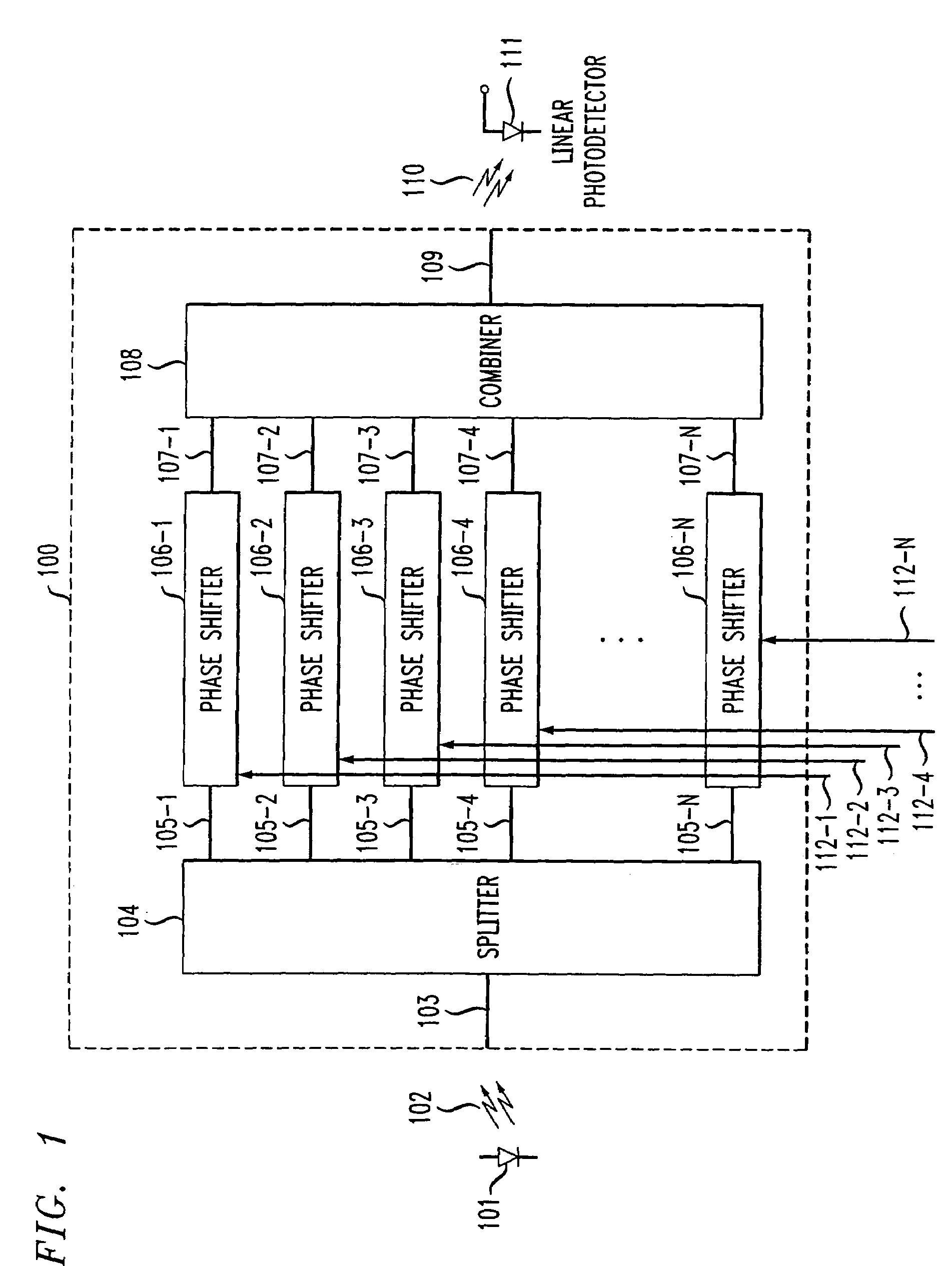
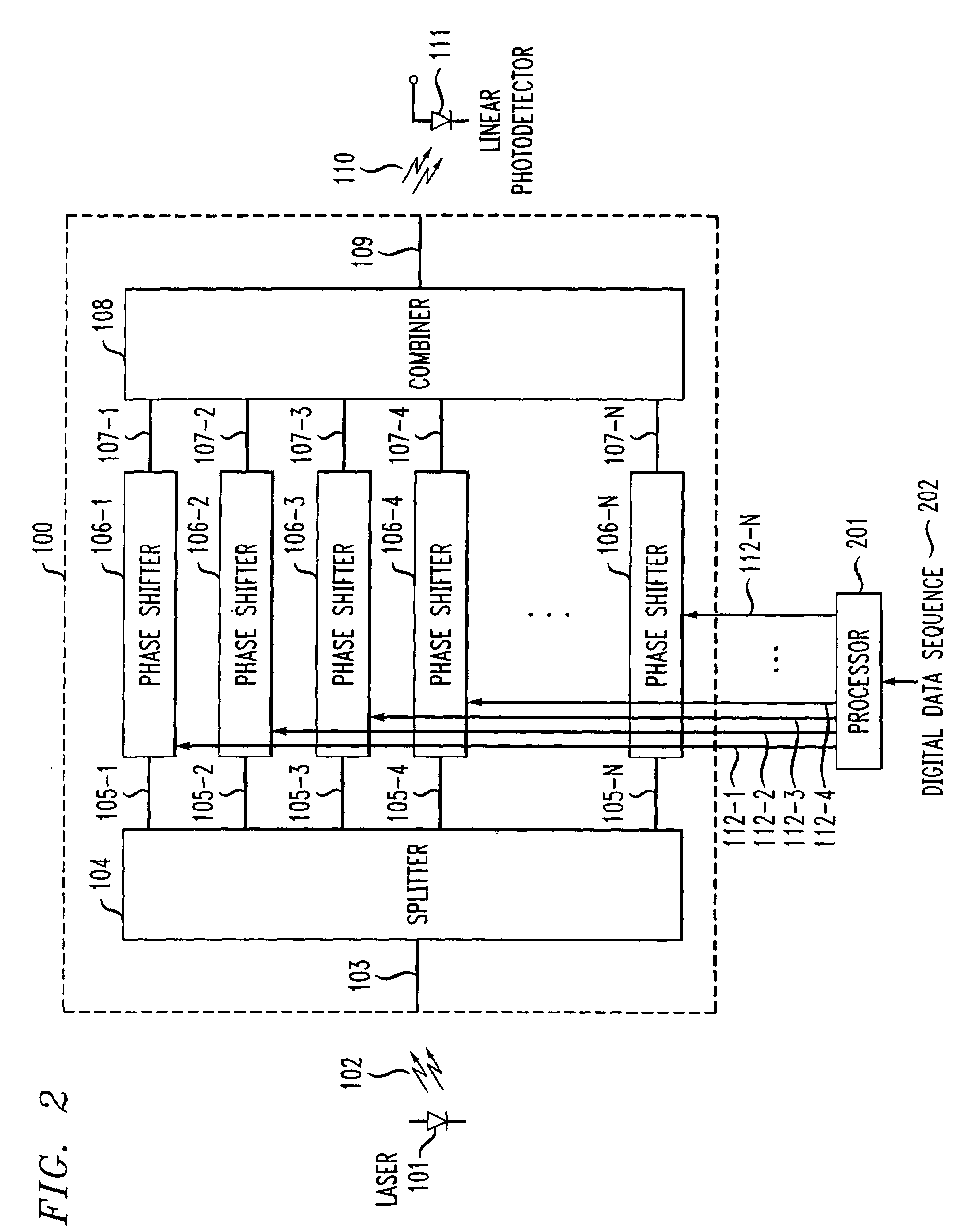
[0019]FIG. 2 also shows, in simplified block diagram form, the invention. The embodiment of FIG. 2 is similar to that of FIG. 1 and includes similar elements that are essentially identical from both a physical and functional standpoint. These similar elements have been similarly numbers as those in FIG. 1 and will not be discussed again in detail. The only significant difference between the embodiments of FIG. 1 and FIG. 2 is the use of processor 201. As can be seen, one or more data signals are supplied to processor 201 via input connection 202. In processor 201, the data signals are employed to code and generate control voltage signals for driving, phase shift modulators 106-1 through 106-N. These control voltage signals are supplied via output connections 112-1 through 107-N to phase shifters 106-1 through 106-N, respectively.

third embodiment

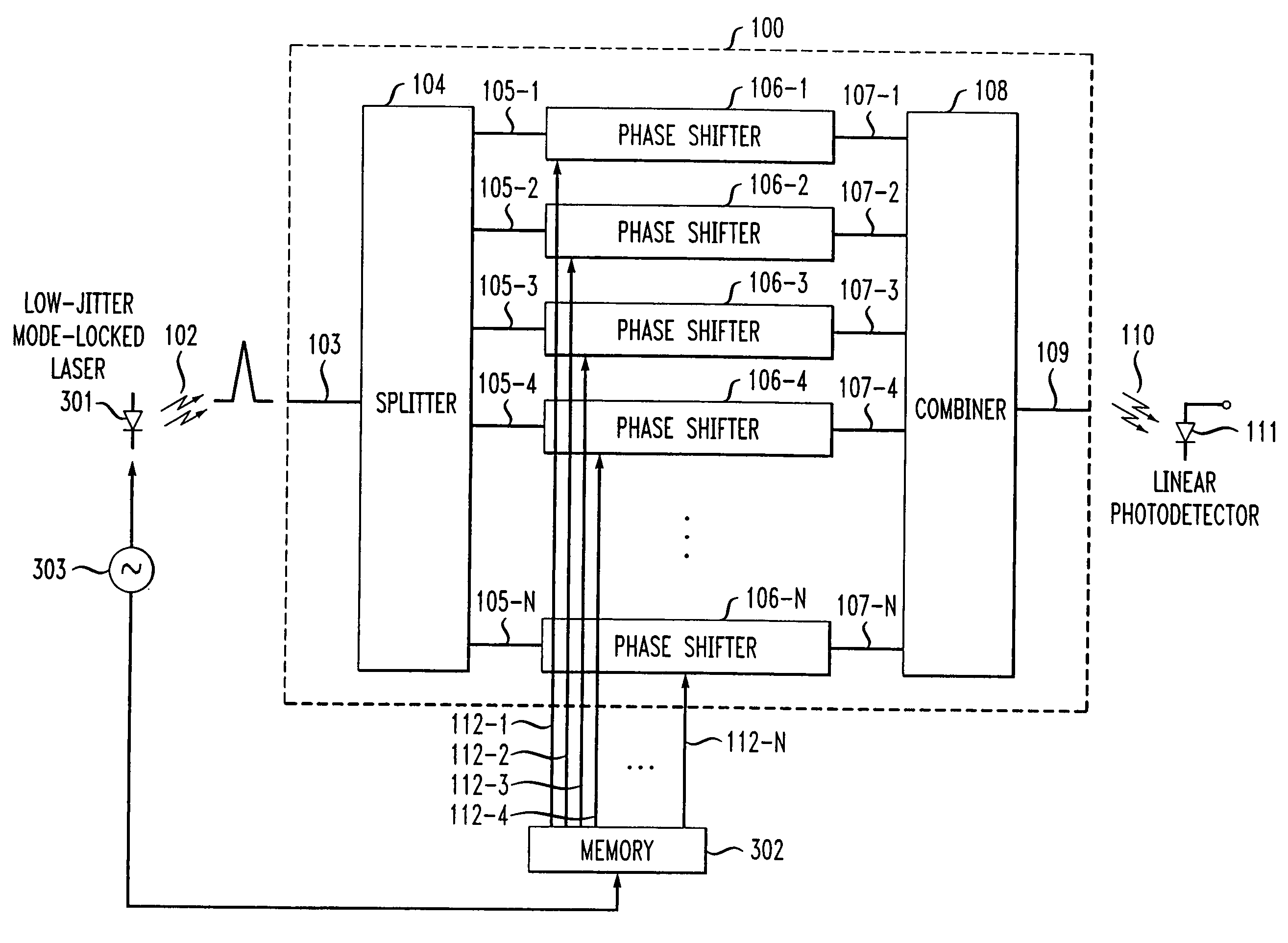
[0020]FIG. 3 illustrates, in simplified block diagram form, the invention. The embodiment of FIG. 3 is also similar to that of FIG. 1 and includes similar elements that are essentially identical from both a physical and functional standpoint. These similar elements have been similarly numbers as those in FIG. 1 and will not be discussed again in detail. The only significant difference between the embodiments of FIG. 1 and FIG. 3 is that a pulsed laser signal is supplied as an input from pulsed laser 301 to the optical digital-to-analog converter 100, and that the pulsed laser optical signal 102 is controlled to have the same repetition rate as the data sequence from memory unit 302. The pulsed laser optical signal is split into a plurality of mutually coherent optical beams 105-1 through 105-N via splitter 104, which are phase shift modulated via phase shifters 106-1 through 106-N by data sequences stored in a memory to generate a substantially jitter free analog optical signal afte...


PUM

PropertyMeasurementUnit
wavelengthaaaaaaaaaa
optical frequenciesaaaaaaaaaa
frequencyaaaaaaaaaa

Abstract

An optical digital-to-analog conversion is realized by employing either a continuous wave or pulsed laser optical signal. The laser optical signal is split into a plurality of mutually coherent optical beams, which are phase shift modulated by bits of a digital data sequence to be converted to an analog signal. The phase shift modulated optical beams are recombined to realize the desired digital-to-analog converted optical signal.

Description

GOVERNMENT CONTRACT[0001]The Government has a paid-up license in this invention and the right in limited circumstances to require the patent owner to license others on reasonable terms as provided for by the terms of Contract No. MDA972-03-C-0046 awarded by DARPA.RELATED APPLICATIONS[0002]U.S. patent application Ser. No. 10 / 133,469 was filed on Apr. 26, 2002, and U.S. patent application Ser. No. 10 / 674,722 was filed on Sep. 3, 2003.TECHNICAL FIELD[0003]This invention relates to optical waveform generation systems and, more particularly, to conversion of digital signals into analog optical signals.BACKGROUND OF THE INVENTION[0004]Digital-to-analog (D / A) converters are key elements in both electronic and photonic signal processing and data transmission. In many optical transmission systems, digital data has to be converted to analog form for processing and / or transmission. Indeed, there are many advantages for using optical technology to implementing D / A converters, for example, high-...

Claims


Application Information

Patent Timeline
Patent Type & Authority Patents(United States)
IPC IPC(8): H03M1/66G02F1/025G02F1/015G02F7/00H04B10/516H04B10/54H04B10/61
CPCG02F7/00G02F2201/18H03M1/66
Inventor CHEN, YOUNG-KAILEVEN, ANDREASTU, KUN-YII
Owner LUCENT TECH INC
Learn More