Electrically small planar antennas with inductively coupled feed

a technology of inductive coupling and electric small antenna, applied in the direction of antenna, antenna details, elongated active element feed, etc., can solve the problems of difficult redesign of complex structures, difficult antenna fabrication, complex antenna structure, etc., to meet different operating frequencies, the input resistance of the antenna, and/or the bandwidth of the antenna may be modified.

Active Publication Date: 2006-06-13
INTELLECTUAL VENTURES HLDG 40
View PDF9 Cites 8 Cited by
  • Summary
  • Abstract
  • Description
  • Claims
  • Application Information

AI Technical Summary

Problems solved by technology

Existing designs for electrically small antennas typically have complicated structures.
Complicated structures may make antenna fabrication difficult.
Complicated structures may also be difficult to redesign to meet different operating frequencies.
The small input resistance may cause difficulty in matching the antenna to the associated radio frequency (RF) system.
However, matching circuits may add to the size, loss, complexity and / or cost of the system.

Method used


Image

  • Electrically small planar antennas with inductively coupled feed
  • Electrically small planar antennas with inductively coupled feed
  • Electrically small planar antennas with inductively coupled feed

Examples


Embodiment Construction

[0017]The design of electrically small antennas may be challenging. For example, typically, as the size of an antenna is reduced, both its efficiency and bandwidth may decrease. Furthermore, the input resistance of an antenna may drop rapidly as the antenna's size is reduced, making impedance matching of the antenna to the rest of the RF system difficult. These issues may impact the overall system performance, especially in high data rate and / or low power consumption devices.

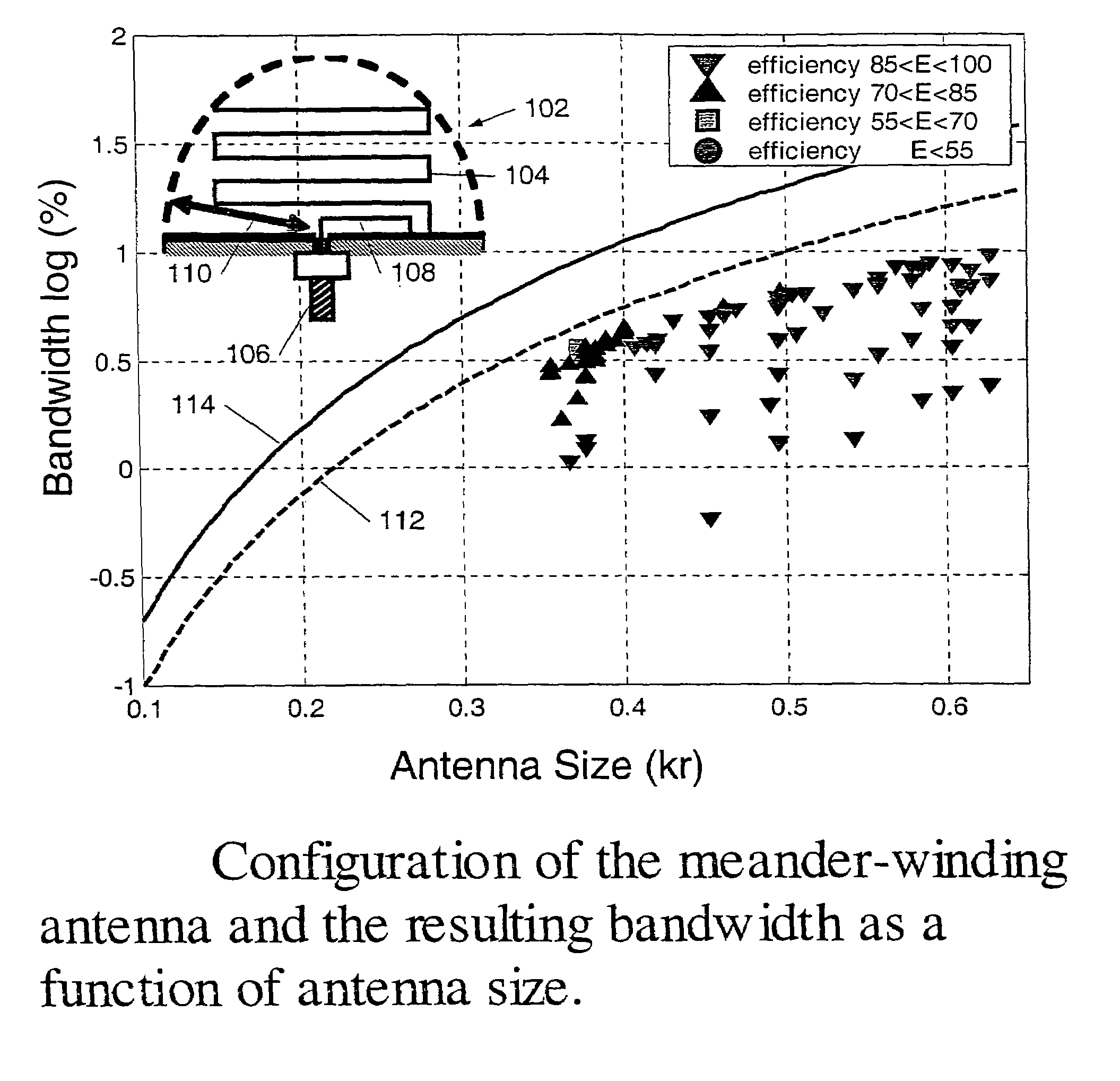
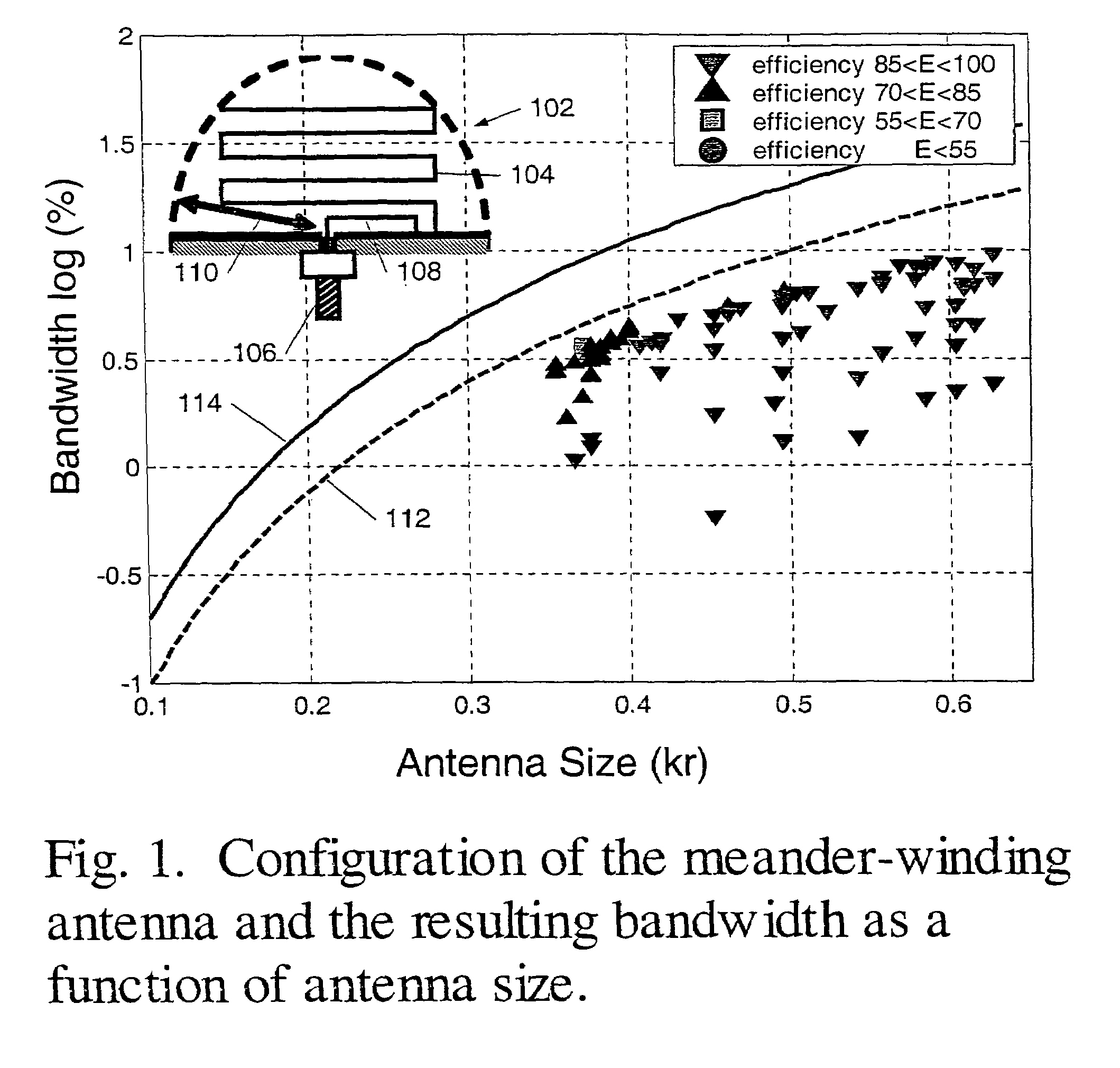
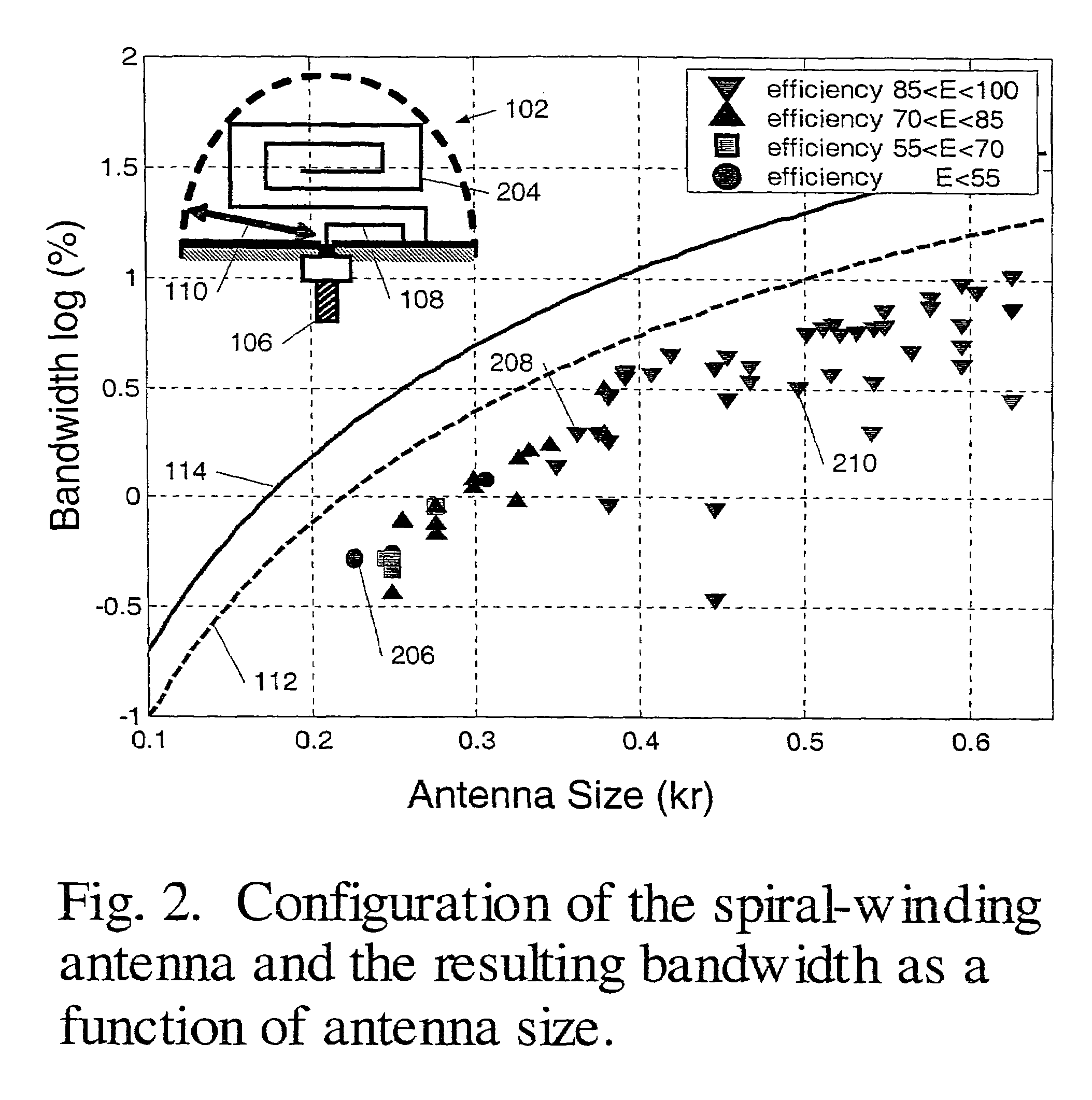
[0018]In an embodiment, relatively small monopole antennas (e.g., kr<0.45 Where k=2π(operating wavelength)) may include a point along the wire that is shorted to a ground plane. One interpretation of this feature may be that a first portion of the wire structure may act as an inductive feed. In such a case, the remaining portion may act as the radiating portion of the antenna. The radiating portion may carry most of the current. This inductive coupling mechanism may tend to increase the input resistance for elec...


PUM


Abstract

Inductively coupled antennas and methods of designing the same are disclosed. Electrically small antennas having relatively high efficiency and relatively broad bandwidth may be formed by inductively coupling an antenna loop to at least one antenna winding. Such antennas may be substantially planar. Various operating characteristics of such antennas may be adjustable by and / or dependent upon the strength of the inductive coupling between an antenna winding and an antenna loop.

Description

PRIORITY CLAIM[0001]This application claims priority to U.S. Provisional Patent Application No. 60 / 477,974 Entitled “Electrically Small Planar Antennas With Inductively Coupled Feed” filed on Jun. 12, 2003.STATEMENT REGARDING FEDERALLY SPONSORED RESEARCH OR DEVELOPMENT[0002]This invention was made with Government support under Contract # N00014-01-1-0224, awarded by the U.S. Office of Naval Research. The Government has certain rights to this invention.BACKGROUND OF THE INVENTION[0003]1. Field of Invention[0004]Embodiments disclosed herein generally relate to methods of designing antennas and antennas designed by those methods. In particular, embodiments relate to antennas with inductively coupled feed.[0005]2. Description of Related Art[0006]Electrically small antennas may include antennas with a size about 10% of the operating wavelength of the antenna or less (e.g., 5% of the operating wavelength). Existing designs for electrically small antennas typically have complicated structu...

Claims


Application Information

Patent Timeline
Patent Type & Authority Patents(United States)
IPC IPC(8): H01Q21/00H01Q1/36H01Q9/42
CPCH01Q1/36H01Q9/42
Inventor CHOO, HOSUNGLING, HAO
Owner INTELLECTUAL VENTURES HLDG 40
Why Eureka
Try Eureka