Method and apparatus for rasterizer interpolation

a technology of interpolation and rasterizer, applied in the field of computer graphics, can solve the problems of reducing the likelihood that one raster will run out of work (or have no work), and achieve the effects of improving efficiency, reducing processing time, and finer level of precision

Active Publication Date: 2006-06-13
ATI TECH INC
View PDF6 Cites 71 Cited by
  • Summary
  • Abstract
  • Description
  • Claims
  • Application Information

AI Technical Summary

Benefits of technology

[0019]The present invention also comprises of a scan converter working in conjunction with a Hierarchical-Z unit in a z-buffer to perform coarse grain tiling. Coarse grain tiling occurs by a series of iterations performed in parallel. Each region undergoes a tiling process where each tile is reduced to a smaller set of sub-tiles, with the goal of reducing time spent on processing empty tiles and/or non-visible tiles with no graphics primitive coverage. With each successive iteration, a finer level of precision is reached. The scan converter communicates with the Hierarchical-Z unit to calculate the current primitive's visibility, using vertex data from the graphics primitive and z depth information. Briefly, in one embodiment, the process starts with computing a list of tiles that are in a current pipeline and covered by a current graphics primitive. Then a first mask value is generated, with the value specifying which of intermediate (smaller) tiles within each of the tiles on the list are visible. Then the process generates a sub-list containing even smaller quad tiles within the intermediate tiles. Following this, a second mask value is c...

Problems solved by technology

This scheme decreases the likelihood that one raster will run out of work (or h...

Method used


Image

  • Method and apparatus for rasterizer interpolation
  • Method and apparatus for rasterizer interpolation
  • Method and apparatus for rasterizer interpolation

Examples


Embodiment Construction

[0041]The invention relates to a rasterizer interpolator. In the following description, numerous specific details are set forth to provide a more thorough description of embodiments of the invention. It will be apparent, however, to one skilled in the art, that the invention may be practiced without these specific details. In other instances, well known features have not been described in detail so as not to obscure the invention.

[0042]Rasterizer Interpolation

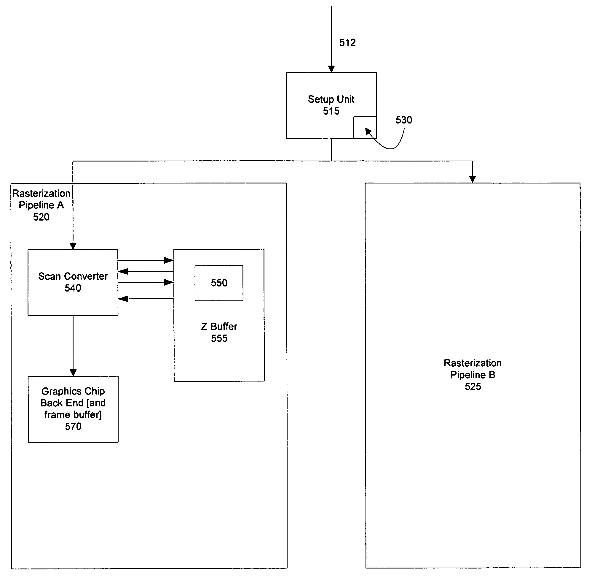
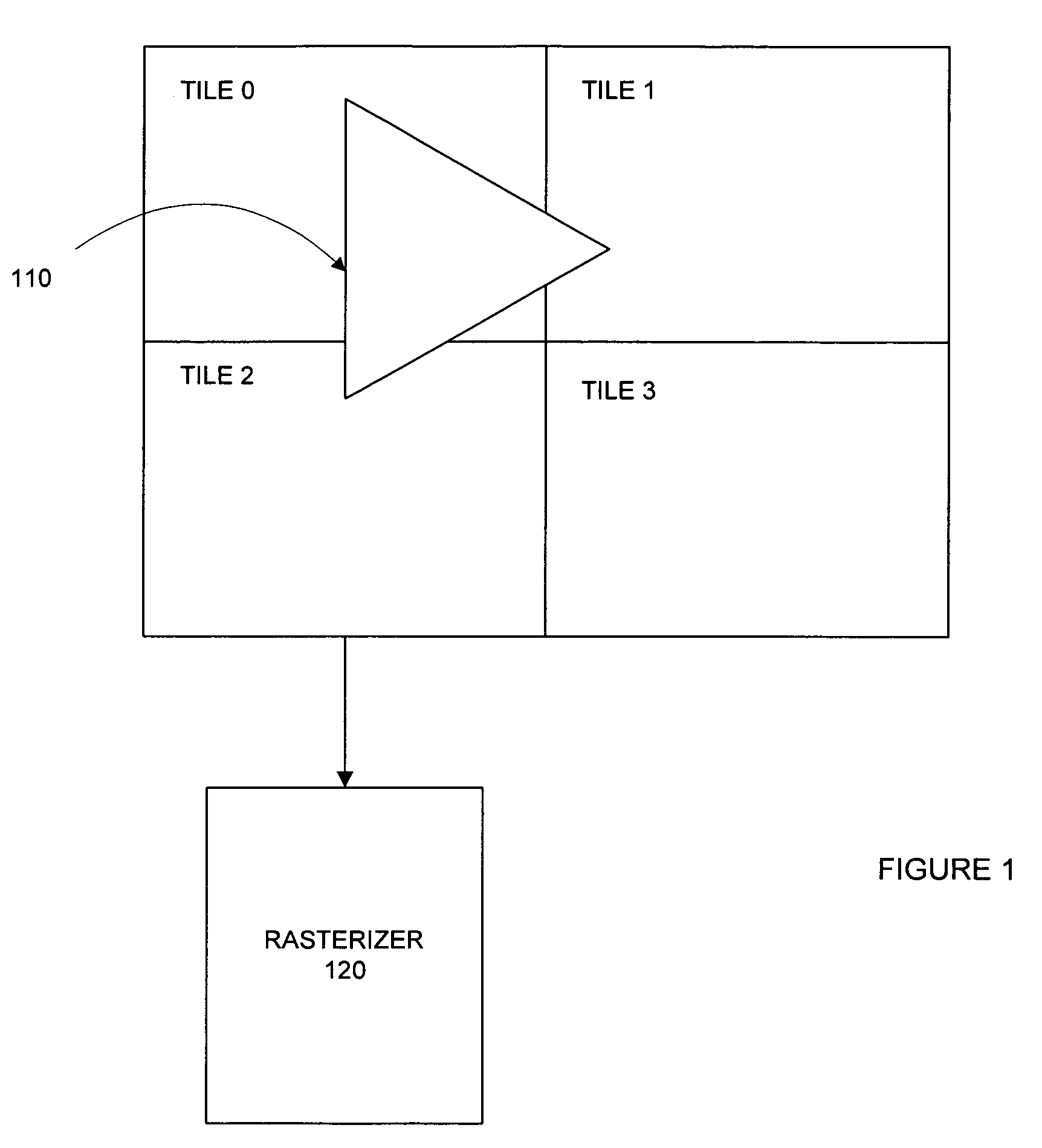
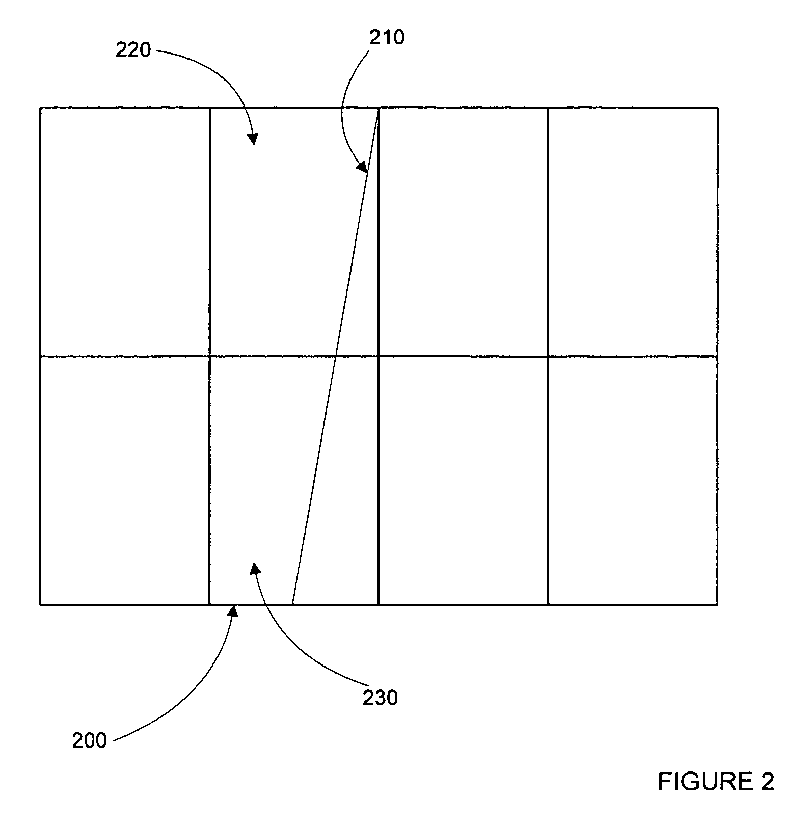
[0043]In one embodiment, multiple parallel rasterizers are used. Each rasterizer is configured to perform its operation at the same time as the other rasterizers, each one executing one or more instructions in each clock cycle. An output screen is divided into a number of regions. For instance, in one embodiment, the screen is sub-divided into four regions and one of four rasterizers is granted ownership of each of the regions. In this way, tiles are interpolated to the appropriate pipelines.

[0044]Coarse grain tiling occurs by ...


PUM


Abstract

The present invention relates to a rasterizer interpolator. In one embodiment, a setup unit is used to distribute graphics primitive instructions to multiple parallel rasterizers. To increase efficiency, the setup unit calculates the polygon data and checks it against one or more tiles prior to distribution. An output screen is divided into a number of regions, with a number of assignment configurations possible for various number of rasterizer pipelines. For instance, the screen is sub-divided into four regions and one of four rasterizers is granted ownership of one quarter of the screen. To reduce time spent on processing empty times, a problem in prior art implementations, the present invention reduces empty tiles by the process of coarse grain tiling. This process occurs by a series of iterations performed in parallel. Each region undergoes an iterative calculation/tiling process where coverage of the primitive is deduced at a successively more detailed level.

Description

[0001]This application is a continuation application of U.S. application Ser. No. 10 / 716,590 filed Nov. 18, 2003, now abandoned which claims priority to U.S. Provisional Application No. 60 / 427,260, filed Nov. 18, 2002.BACKGROUND OF THE INVENTION[0002]1. Field of the Invention[0003]The present invention relates computer graphics. More specifically, one or more embodiments of the present invention relate to a rasterizer interpolator.[0004]Portions of the disclosure of this patent document contain material that is subject to copyright protection. The copyright owner has no objection to the facsimile reproduction by anyone of the patent document or the patent disclosure as it appears in the Patent and Trademark Office file or records, but otherwise reserves all copyright rights whatsoever.[0005]2. Background Art[0006]Display images are made up of thousands of tiny dots, where each dot is one of thousands or millions of colors. These dots are known as picture elements, or “pixels”. A ras...

Claims


Application Information

Patent Timeline
IPC IPC(8): G06T1/20
CPCG06T11/40
Inventor LEATHER, MARK M.
Owner ATI TECH INC
Why Eureka
Try Eureka