

Zoom lens, and electronic apparatus using the same
a technology of electronic equipment and zoom lens, which is applied in the direction of cameras, television systems, instruments, etc., can solve the problems of large distortion at the wide-angle end, inability to satisfactorily ensure the back focus, and inability to compact the camera in height and width, so as to reduce the amount of movement, suppress distortion, and increase the diameter of the front element.
- Summary
- Abstract
- Description
- Claims
- Application Information
AI Technical Summary
Benefits of technology
Problems solved by technology
Method used
Image

Examples
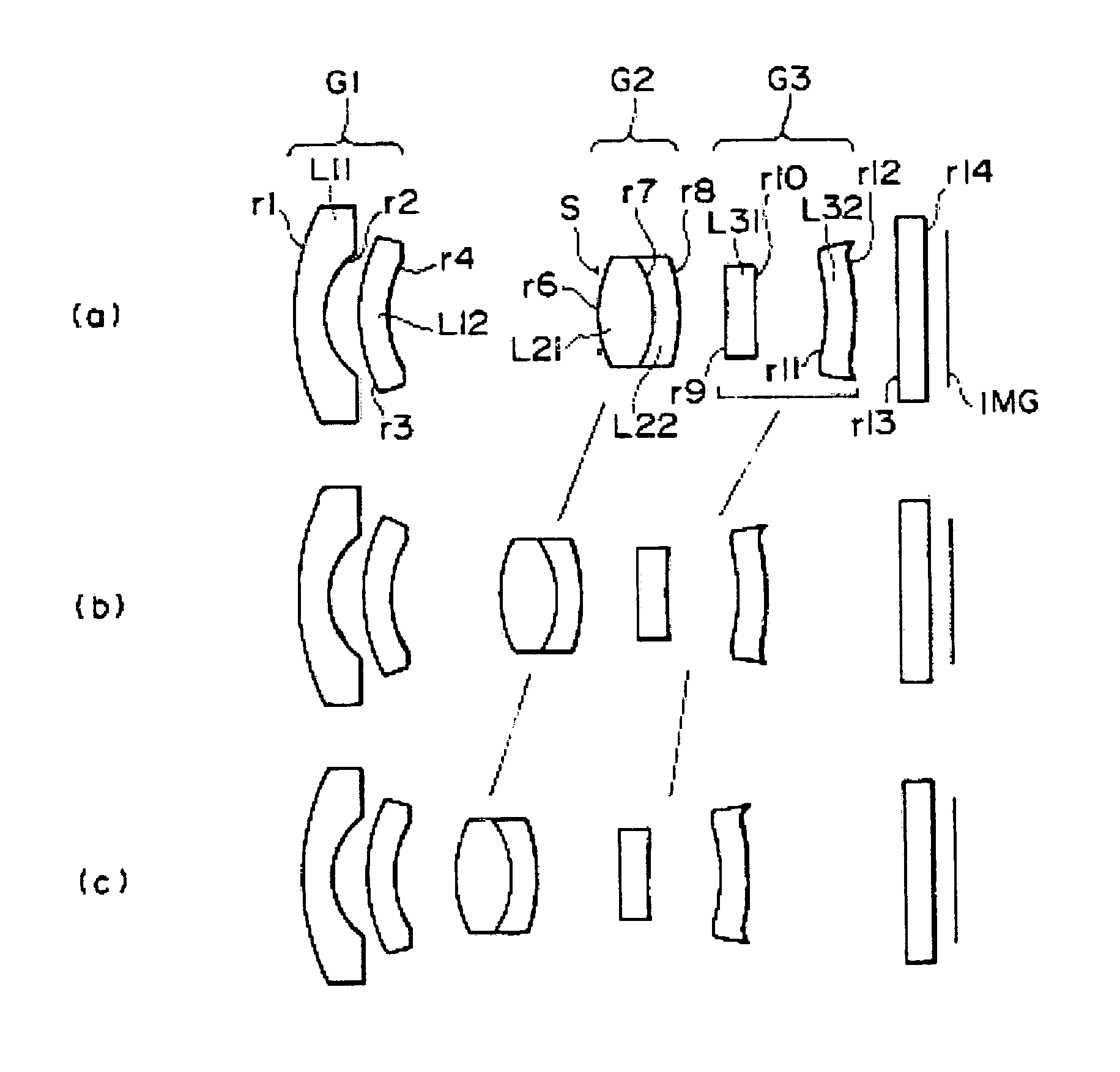
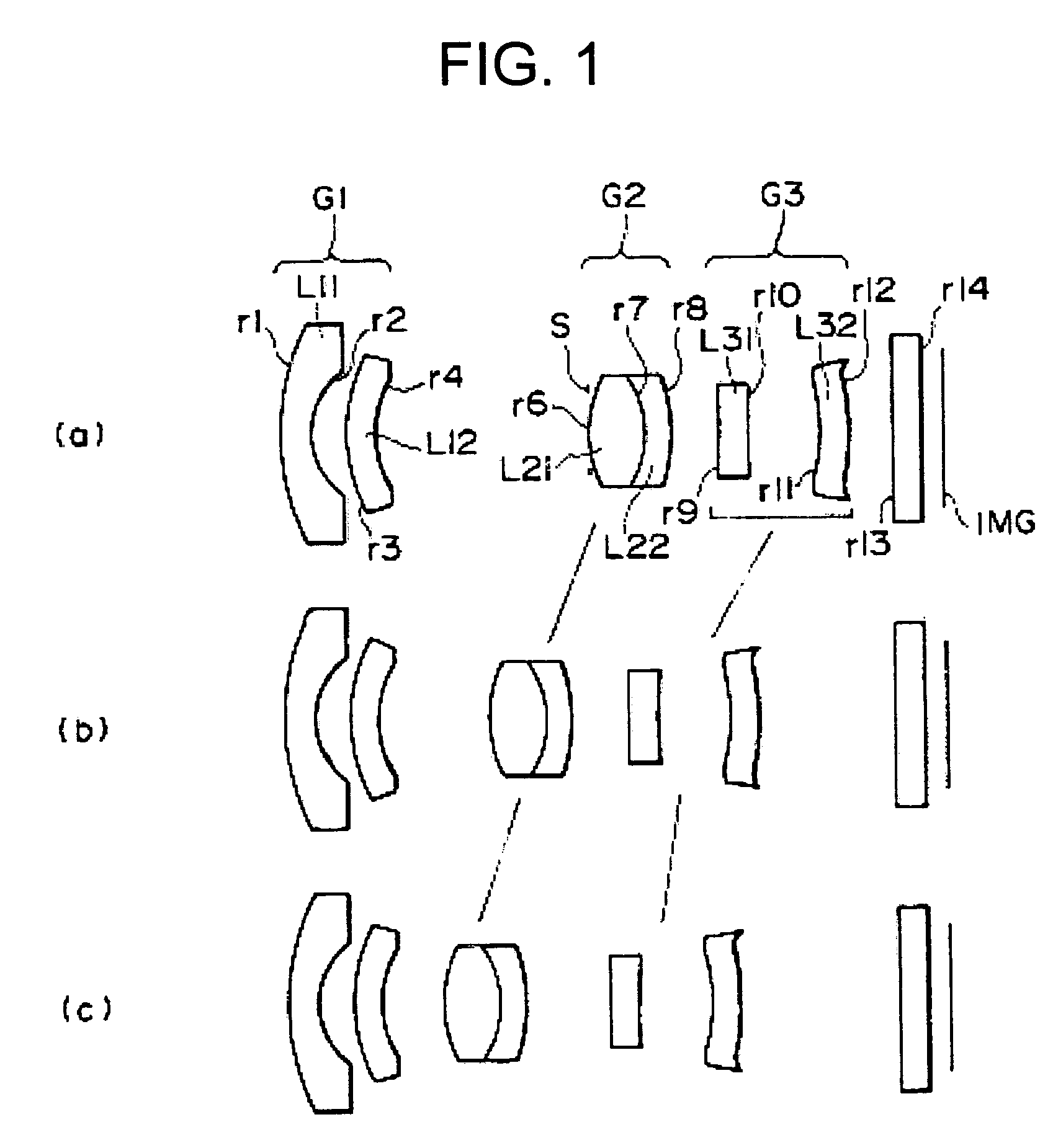
first embodiment
[0051]Table 1 shows specific values in the lens of the The surface numbers shown in Table 1 respectively correspond to numbers r1 to r14 of the lens surfaces shown in FIG. 1, and R represents the radius of curvature of a lens surface, and D represents the space between adjacent two lens surfaces. N represents a refractive index relative to the d line, and Vd represents an Abbe's number.
[0052]
TABLE 1SURFACENUMBERRDNdVd14.6360.51.516864.221.4000.633.0330.51.5299655.941.852ADIAPHRAGMINFINITY0.1762.1780.971.693553.27−1.8460.451.755227.58−3.157B9−4.3730.51.8211424.1109.7061.2211−3.4950.51.5299655.912−4.623C13INFINITY0.51.516864.214INFINITY0.35
[0053]Of the above-listed values, D4, D8 and D12 are respectively shown by variables A, B and C, because the respective spaces vary with zooming. The values of the respective variables A, B and C of the first embodiment which are obtained when zooming from the wide-angle end to the telescopic end is performed are shown in Table 2. In Table 2, f pre...
second embodiment
[0061]Table 4 shows specific values in the lens of the The surface numbers shown in Table4respectively correspond to the numbers r1 to r14 of the lens surfaces shown in FIG. 5, and R represents the radius of curvature of a lens surface and D represents the space between adjacent two lens surfaces. N represents a refractive index relative to the d line, and Vd represents an Abbe's number.
[0062]
TABLE 4SURFACENUMBERRDNdVd15.0310.51.48770.421.4000.83147.9040.6247131.5138656.4432.489ADIAPHRAGMINFINITY0.17037162.4710.9474411.693553.27−1.3740.451.7854139.28−2.662B923.7450.51.8211424.1102.5451.2400611−3.9770.500051.5138656.412−4.000C13INFINITY0.51.516864.214INFINITY0.35
[0063]Of the above-listed values, D4, D8 and D12 are respectively shown by variables A, B and C, because the respective spaces vary with zooming. The values of the respective variables A, B and C of the second embodiment which are obtained when zooming from the wide-angle end to the telescopic end is performed are shown in T...
PUM
 Abstract
Description
Claims
Application Information