
Apparatus, program and method for detecting both stationary objects and moving objects in an image using optical flow

an object detection and optical flow technology, applied in image analysis, image enhancement, instruments, etc., can solve the problems of inability to accurately detect stationary objects by this method, inability to detect stationary objects accurately, and inability to compensate the optical flow of stationary objects in the background of input images, so as to improve the accuracy of extracting flow features and improve the possibility area of objects

Active Publication Date: 2006-06-13
HONDA MOTOR CO LTD
View PDF6 Cites 41 Cited by
  • Summary
  • Abstract
  • Description
  • Claims
  • Application Information

AI Technical Summary

Benefits of technology

[0013]Since the flow information generated by the motion of the mobile unit may be removed from the input images, the apparatus may detect objects in the input images high-accurately. The computing load may be small because the determination is done only for the extracted “figure” part of the input images. “New flow information” refers to “a feedback local flow”, which is described in preferred embodiments.
[0022]Extracting local areas by the flow feature calculator is preferably repeated twice. In other words, the local areas extracted by flow feature calculator are preferably processed again by the global flow processor and the flow feature calculator as described above. It is possible to extract the local areas having different flow direction from the one generated by the estimated motion of the mobile unit. By performing the object presence determination process on this repeatedly extracted local areas, the accuracy of the extracting flow features and object presence possibility area may be improved.

Problems solved by technology

However, when an imaging device itself for capturing images moves (for example, an imaging device is mounted on an automobile), it is difficult to detect moving objects by above-described approach because optical flow is also generated by the motion of the imaging device.
However, optical flow of stationary objects in background of the input images would not be compensated because they would be considered as a background by this method.
Therefore, it is impossible by this method to detect stationary objects accurately.
However, it is difficult to segment the optical flow of the objects from that of the background and such accurate segregating technique has not been realized.

Method used


Image

  • Apparatus, program and method for detecting both stationary objects and moving objects in an image using optical flow
  • Apparatus, program and method for detecting both stationary objects and moving objects in an image using optical flow
  • Apparatus, program and method for detecting both stationary objects and moving objects in an image using optical flow

Examples


Embodiment Construction

[0047]Preferred embodiments of the invention are described in reference to the attached drawings.

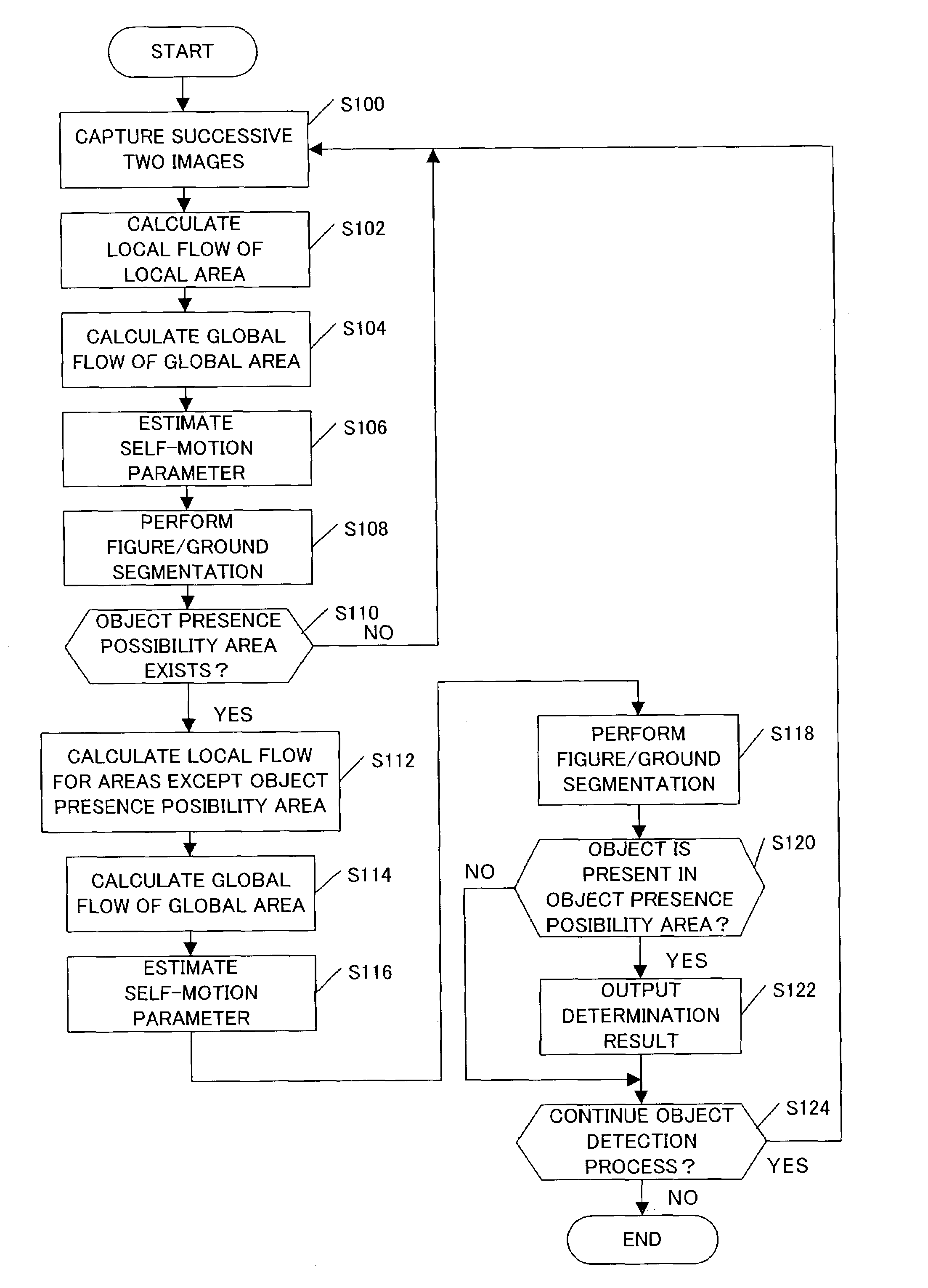
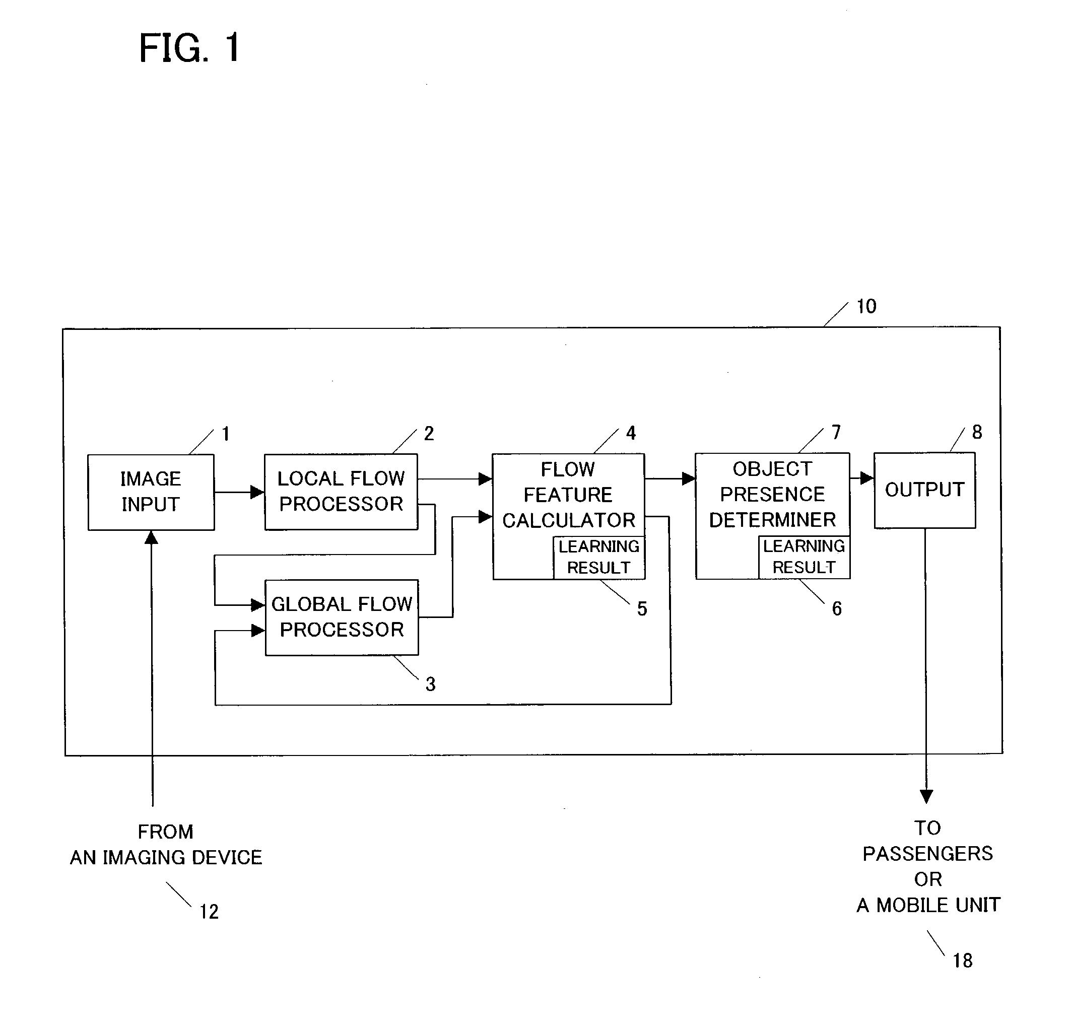
[0048]FIG. 1 shows a block diagram of an object detection apparatus 10 of the invention. The object detection apparatus 10 receives input images (scenes) of traveling direction of a mobile unit, such as autonomous traveling automobile, captured by an imaging device 12 such as a CCD camera at predetermined intervals. The object detection apparatus 10 then determines whether there are some objects obstructing the travel of the mobile unit based on the input images, and outputs the result of the determination, which is sent to a motor or steering of the mobile unit. The mobile unit decelerates, stops, or avoids the object in response to the output. Alternatively, the presence of the object obstructing the travel of the mobile unit may be informed to passengers on the autonomous travel automobile.

[0049]The object detection apparatus 10 may be implemented by a microcomputer comprising a CPU f...


PUM


Abstract

An object detection apparatus is provided for detecting both stationary objects and moving objects accurately from an image captured from a moving mobile unit.The object detection apparatus of the present invention applies Gabor filter to two or more input images captured by an imaging device such as CCD camera mounted on a mobile unit, and calculates optical flow of local areas in the input images. Then the object detection apparatus closely removes optical flow produced by motion of the mobile unit by estimating optical flow produced from background of the input images. In other words, the object detection apparatus clarifies the area where object is not present (“ground”) in the input images. By removing such “ground” part, the area where objects seems to be present (“feature”) is extracted from the input images. Finally, the object detection apparatus determines whether objects are present or not using flow information of the extracted “feature” part.

Description

TECHNICAL FIELD[0001]The present invention relates to detecting objects in input images. In particular, the invention relates to an object detection apparatus, program and method for detecting both stationary objects and moving objects in input images captured from a mobile unit.BACKGROUND OF THE INVENTION[0002]There are some conventional approaches for detecting objects based on input images. According to one approach, optical flow is first calculated from captured images and a part corresponding to an object is then extracted from the area having the same motion component. Since moving objects in the image may be easily detected by this approach, some object detection apparatuses based on this approach are known in the art (for example, Japanese Patent Application Unexamined Publication (Kokai) No. 7-249127).[0003]However, when an imaging device itself for capturing images moves (for example, an imaging device is mounted on an automobile), it is difficult to detect moving objects ...

Claims


Application Information

Patent Timeline
IPC IPC(8): G06K9/00G06T7/00G08G1/16G06T7/20
CPCG06T7/0044G06T7/2006G06T7/2066G06T7/206G06T2207/30241G06T7/74G06T7/215G06T7/262G06T7/269
Inventor TSUJINO, HIROSHIKONDO, HIROSHIMIURA, ATSUSHINAGAI, SHINICHIAKATSUKA, KOJI
Owner HONDA MOTOR CO LTD
Learn More