System and method for optimizing color compression using transparency control bits

a transparency control and color compression technology, applied in the field of data compression schemes, can solve the problems of increasing the time required for the printer's data pipeline to transmit data, the inability to provide enough and the inability to provide byte-based compression methods with the reduction of storage space or transmit time that may be required, so as to achieve the effect of longer run length

Inactive Publication Date: 2006-06-13
RICOH KK
View PDF19 Cites 33 Cited by
  • Summary
  • Abstract
  • Description
  • Claims
  • Application Information

AI Technical Summary

Benefits of technology

[0020]According to this embodiment, the selected pixel position defines a portion of the display area region comprising pixels having color data that is not used to contribute to a color of the first object or the second object. Switching the color data does not occur upon encountering a non-transparent pixel location if the second color code is equal to the first color code. In one particular embodiment, the selected pixel position is determined using a count of arbitrary data corresponding to a number of transparent pixels encountered and a count of repeat data corresponding to a number of non-transparent pixels encountered. Upon encountering a non-transparent pixel having color data equal to that of the transparent pixels, the color code associated with the arbitrary data is set to the color code of the non-transparent pixel, so as to achieve a longer run length.

Problems solved by technology

One of the major limitations in increasing printer speed is the time required to rasterize print data, especially the time required by the raster image processor to break an image into different object components and then reassemble, screen and merge those components into a final bitmap image.
As printers increase the density of dot placements, particularly with color printing that requires additional bits per pixel over monochrome printing, the time required for the printer's data pipeline to transmit the data becomes substantial.
Such a byte-based compression method may still not provide enough reduction in storage space or transmit time that may be required by current print engines.
Further, conventional compression methods may not be targeted to handle multiple bits / pixel.
Moreover, prior compression methods may not be efficient in terms of compressing color data.

Method used


Image

  • System and method for optimizing color compression using transparency control bits
  • System and method for optimizing color compression using transparency control bits
  • System and method for optimizing color compression using transparency control bits

Examples


Embodiment Construction

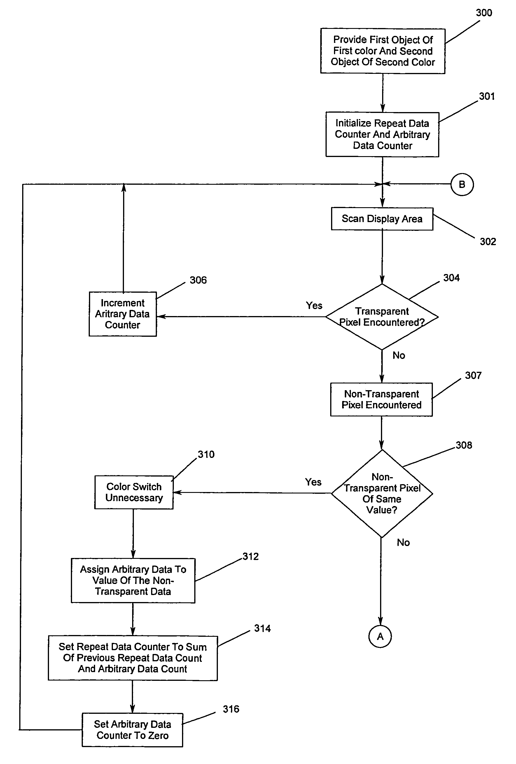
[0034]In the following description of the illustrated embodiments, references are made to the accompanying drawings which form a part hereof, and in which is shown by way of illustration, various embodiments in which the invention may be practiced. It is to be understood that other embodiments may be utilized, and structural and functional changes may be made without departing from the scope of the present invention.

[0035]A system and methodology in accordance with the principles of the present invention provide for increased compression of color data over prior art approaches, which reduces memory access times and required bandwidth, and minimizes data transfer time between a raster image processor and a color interface card. A color compression approach consistent with the principles of the present invention provides for improved throughput when handling complex color data in microcode, which is particularly advantageous when compressing the data of merged objects.
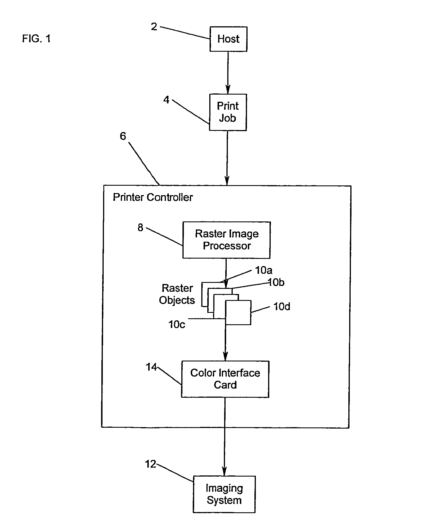
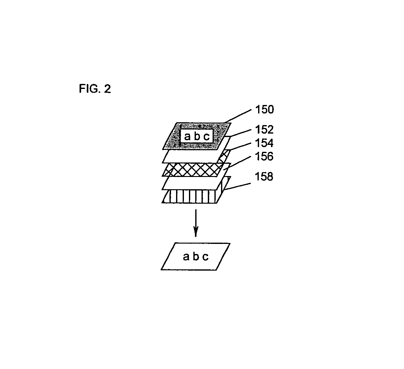
[0036]Turning no...


PUM


Abstract

A system, method, and processor-readable medium provide for compressing color data involves a number of pixels defining a region of a display area. The pixel data for each of the pixels includes color data and control data. The control data of particular pixels, having color data not used to contribute to a color of an object in a display area region, is set to a transparent setting. The color data of the particular pixels is set to a selected color code for the entire region and subject to compression. In another embodiment, the particular pixels may include color data not used to contribute to a color of a first object or a second object in the display area region. The color data of particular pixels defining the first object is set to a first color code. The color data of particular pixels defining the second object is set to a second color code. The color data is switched between the first and second color codes at a selected pixel position. The color data of the particular pixels for the first and second display areas is compressed using the respective first and second color codes. Color compression may involve merging the second object of the second color with the first object of the first color.

Description

CROSS-REFERENCE TO RELATED APPLICATIONS[0001]This application is related to the following co-pending and commonly-assigned patent applications, all of which are filed on the same date herewith:[0002]“Color Image Data and Control Bit Compression Scheme with Run Length Encoding,” to Jean M. Aschenbrenner, Stephen D. Hanna, and John T. Varga, now, U.S. Pat. No. 6,721,456, issued Apr. 13, 2004;[0003]“Method, System, Program, and Data Structure for Generating Raster Objects,” to Jean M. Aschenbrenner, Christopher Kush, and John T. Varga, U.S. application Ser. No. 09 / 569,777, filed May 12, 2000, now U.S. Pat. No. 6,850,358, issued Feb. 1, 2005;[0004]“Method, System, and Logic for Selecting Line Work and Control Data for a Pixel from Multiple Objects of Line Work Data Provided for the Pixel” to David E. Finlay and Phillip K. Hoskins, U.S. application Ser. No. 09 / 570,211, filed May, 12, 2000, now U.S. Pat. No. 6,894,796, issued May 17, 2005.[0005]“System and Method for Merging Line Work Obj...

Claims


Application Information

Patent Timeline
Patent Type & Authority Patents(United States)
IPC IPC(8): G06K9/36H04N1/32
CPCH04N1/642H04N1/41
Inventor VARGA, JOHN T.
Owner RICOH KK
Why Eureka
Try Eureka