
Negative working, heat-sensitive lithographic printing plate precursor

Inactive Publication Date: 2005-10-27
AGFA NV
View PDF19 Cites 9 Cited by
  • Summary
  • Abstract
  • Description
  • Claims
  • Application Information

AI Technical Summary

Benefits of technology

[0012] It is an object of the present invention to provide a negative-working heat-sensitive lithographic printing plate precursor for making in a convenient way a lithographic printing plate which has excellent printing properties-i.e. high image quality and no toning-and which allows a long run-length. It is a further object of the present invention to provide a method for obtaining in a convenient way a negative-working heat-sensitive lithographic printing plate with a high run-length which provides prints without toning and with an excellent image quality, by using said precursor.
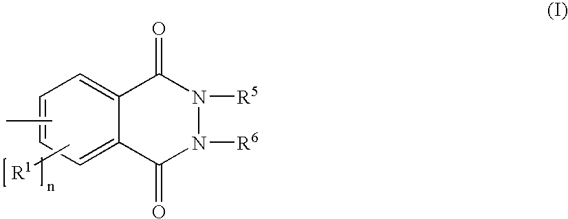
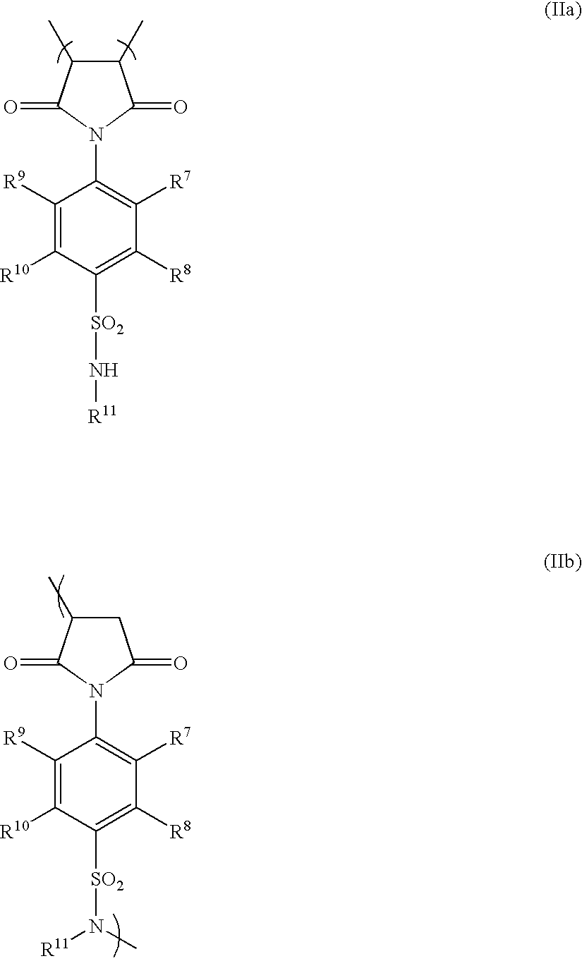
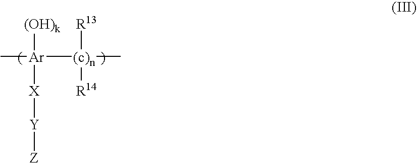
[0017] According to the present invention it was surprisingly found that a printing plate precursor comprising the specific combination of a phenolic resin (present in a first layer) and a polymer comprising at least one sulphonamide group (present in a layer below said first layer), provides a printing plate with a high run-length that gives prints with an excellent image quality and no toning.
[0020] (ii) imagewise exposing the coating to heat and / or infrared light, thereby reducing the capacity of said coating of being penetrated and / or solubilized by an aqueous alkaline solution,

Problems solved by technology

The major problems associated with the prior art plate materials which work according to heat-induced latex coalescence are the low run-length which is due to the ease of mechanical damage of the coating of such materials, the low chemical resistance against press liquids and / or the poor image quality.

Method used


Image

  • Negative working, heat-sensitive lithographic printing plate precursor
  • Negative working, heat-sensitive lithographic printing plate precursor
  • Negative working, heat-sensitive lithographic printing plate precursor

Examples


invention examples 10-13

Preparation of the Lithographic Base.

[0136] The preparation of the lithographic support for the Invention Examples 10-13 was carried out in the same way as described for the Comparative Examples 2-7 and Invention Examples 8 and 9.

Preparation of the Printing Plate Precursors 10-14.

[0137] The printing plate precursors were produced by first coating the coating defined in Table 9 onto the above described lithographic base. The coating solution (comprising a mixture of isopropanol / water for Invention Examples 11 and 13 and for Invention Examples 10 and 12 only water) was applied at a wet coating thickness of 30 μm and then dried at 130° C. for two minutes. The dry coating weight was 0.5 g / m2 for invention Examples 10 and 11 and 0.1 g / m2 for invention Examples 12 and 13.

TABLE 9Composition of the first coating (g / m2).InventionInventionInventionInventionExampleExampleINGREDIENTS GExample 10Example 111213Flexo-blau 630 (1)0.020.020.020.02SP-01 (2)0.480.480.980.98

(1) Flexo-blau 630 St...

invention example 14

[0142] The printing plate precursor of Invention Example 13 was mounted on a Sakmai Oliver 52 press using K+E Novavit 800 Skinnex available from BASF Drucksysteme GmbH as ink and Emerald premium 4% as fountain. After 100,000 prints the 1% highlight of a 200 lpi screen was still rendered on the print indicating an excellent run lenght resistance.


PUM


Abstract

A negative-working lithographic printing plate precursor is disclosed comprising on a support having a hydrophilic surface or which is provided with a hydrophilic layer, a coating comprising an infrared absorbing agent, a first layer comprising an aqueous dispersion comprising hydrophobic thermoplastic polymer particles and a first hydrophobic binder, and a second layer located between said first layer and said support which comprises a second hydrophobic binder, characterized in that said first hydrophobic binder is a phenolic resin and said second hydrophobic binder is a polymer comprising at least one sulphonamide group.

Description

[0001] The application claims the benefit of U.S. Provisional Applications No. 60 / 570,767 filed May 13, 2004 and No. 60 / 579,618 filed Jun. 15, 2004.FIELD OF THE INVENTION [0002] The present invention relates to a heat-sensitive, negative working lithographic printing plate precursor. BACKGROUND OF THE INVENTION [0003] Lithographic printing presses use a so-called printing master such as a printing plate which is mounted on a cylinder of the printing press. The master carries a lithographic image on its surface and a print is obtained by applying ink to said image and then transferring the ink from the master onto a receiver material, which is typically paper. In conventional, so-called “wet” lithographic printing, ink as well as an aqueous fountain solution (also called dampening liquid) are supplied to the lithographic image which consists of oleophilic (or hydrophobic, i.e. ink-accepting, water-repelling) areas as well as hydrophilic (or oleophobic, i.e. water-accepting, ink-repel...

Claims


Application Information

Patent Timeline
IPC IPC(8): B41C1/10G03C1/492
CPCB41C1/1025B41C2201/04B41C2201/02B41C2201/14Y10S430/145B41C2210/06B41C2210/22B41C2210/24B41C2210/262B41C2210/04
Inventor VERMEERSCH, JOANVAN DAMME, MARC
Owner AGFA NV
Learn More