Radio transmission apparatus and radio reception apparatus

Inactive Publication Date: 2006-06-13
PANASONIC CORP
View PDF13 Cites 11 Cited by
  • Summary
  • Abstract
  • Description
  • Claims
  • Application Information

AI Technical Summary

Benefits of technology

[0009]It is an object of the present invention to provide a radio transmission apparatus and radio reception apparatus enabling the reception apparatus to receive signals of high quality using a single antenna and further to receive signals of high quality even when received electric field strengths are weak in a modulation system that changes a plane of polarization of a polarization.
[0010]It is a subject matter of the present invention that with respect to a variation in received electric

Problems solved by technology

Digital radio communications always have a possibility that a received electric field strength of a signal becomes weak due to geographical conditions because a space is used as a transmission medium.
Therefore, when the received electric field strength of the signal is weak, an error rate of data is increased and the data quality deteriorates.
However, in the technique, when a signal transmitted, for example, from a dextro-antenna is reflected by a wall or the like, the polarization of the signal is changed and the signal is converted to a signal transmitt

Method used


Image

  • Radio transmission apparatus and radio reception apparatus
  • Radio transmission apparatus and radio reception apparatus
  • Radio transmission apparatus and radio reception apparatus

Examples


first embodiment

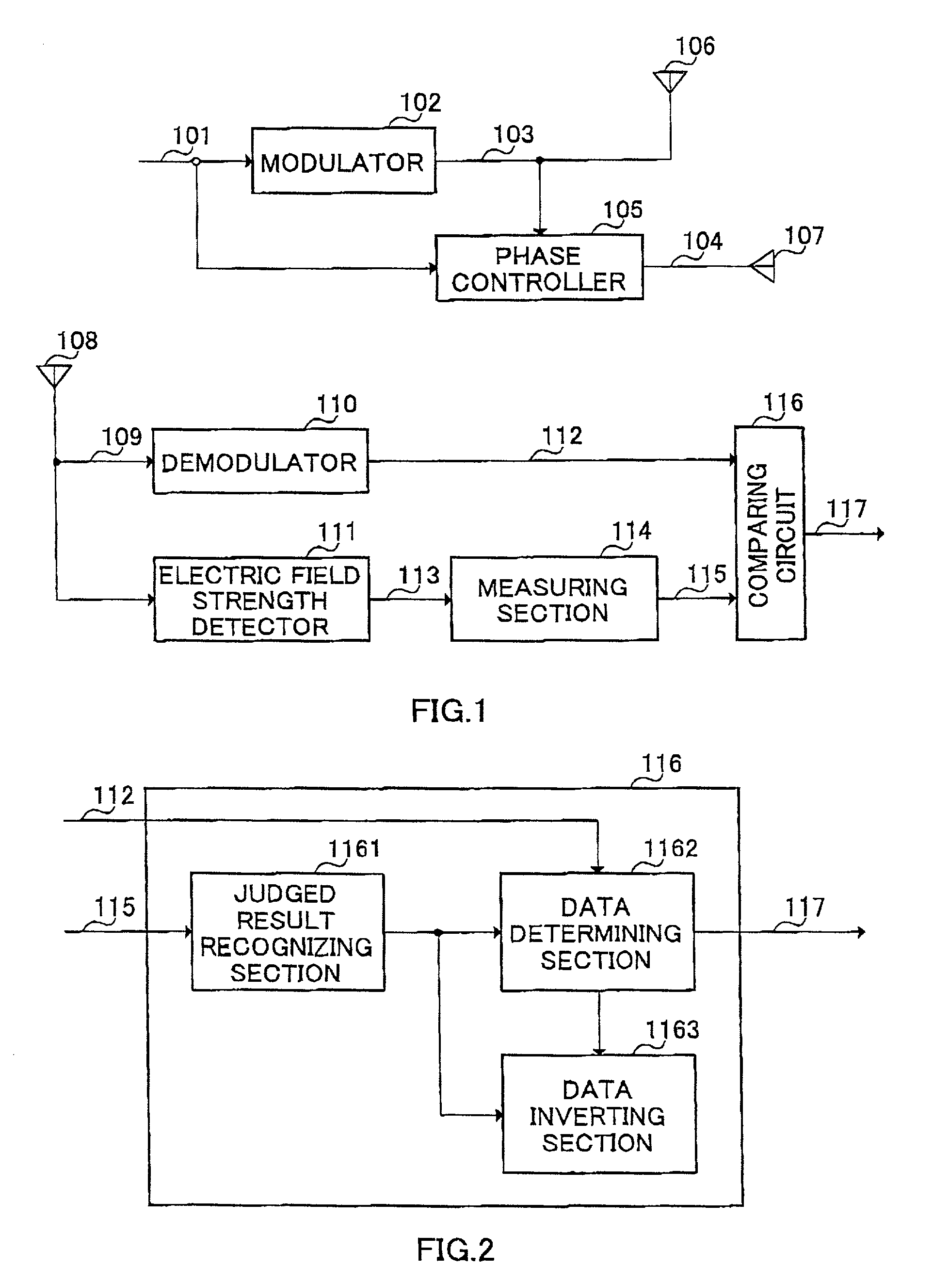
[0023]This embodiment explains a radio transmission apparatus and reception apparatus in which planes of polarization are switched depending on transmission data. FIG. 1 is a block diagram illustrating configurations of the radio transmission apparatus and radio reception apparatus according to the first embodiment of the present invention.

[0024]Transmission data 101 is converted into modulated signal 103 in modulator 102, and the signal 103 is transmitted through first linear polarization antenna element 106. Phase controller 105 has a control terminal, and through the terminal, receives transmission data 101 and modulated signal 103 from modulator 102.

[0025]Phase controller 105 converts modulated signal 103 corresponding to transmission data 101 into modulated signal 104 with the same phase or with a phase shifted 180°. Modulated signal 104 is transmitted through second linear polarization antenna element 107. That is, phase controller 105 provides a 180 degrees phase difference t...

second embodiment

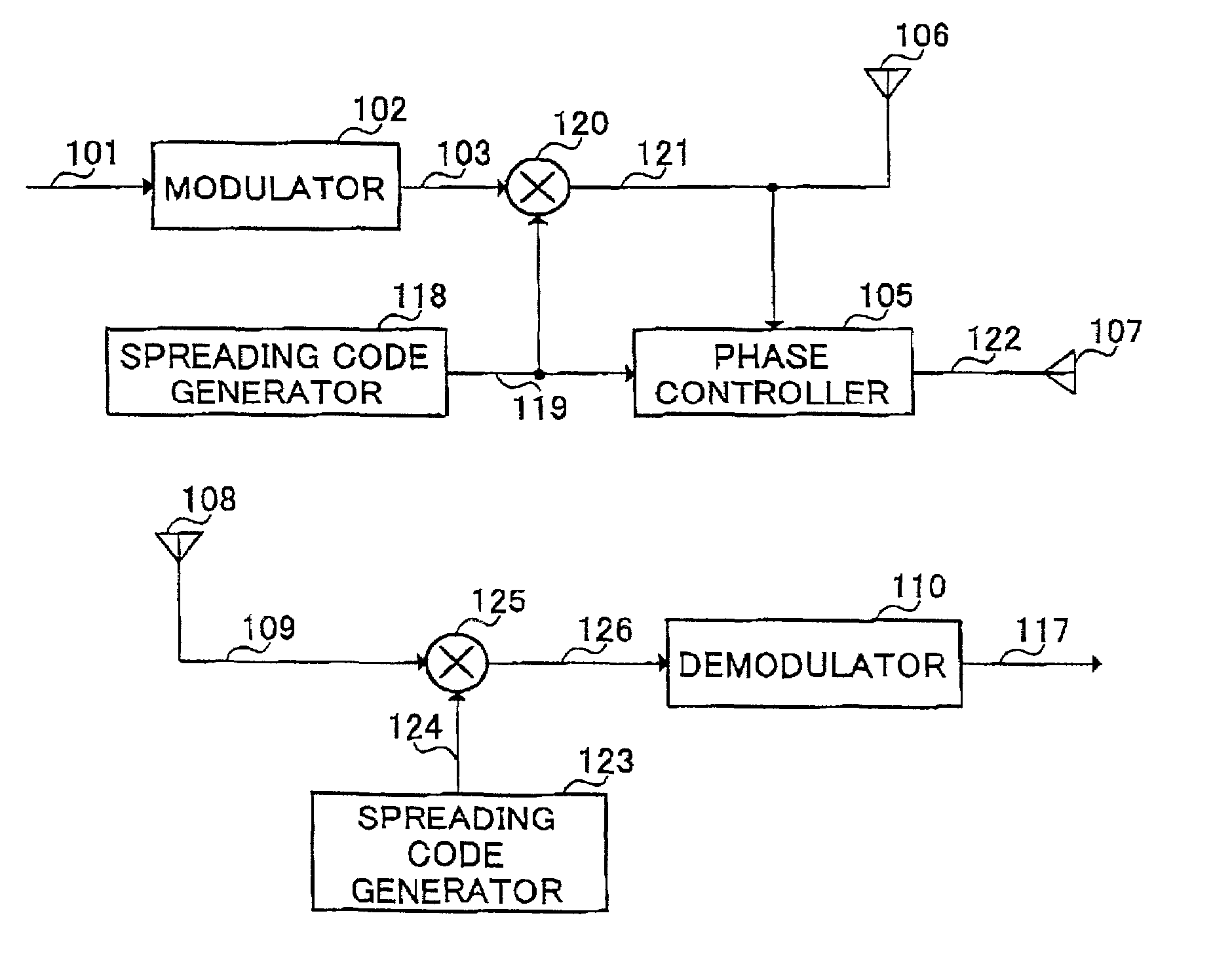
[0060]This embodiment explains a radio transmission apparatus that switches planes of polarization using a spreading code. FIG. 8 is a block diagram illustrating configurations of the radio transmission apparatus and a radio reception apparatus according to the second embodiment of the present invention.

[0061]In this embodiment, phase controller 105 receives its inputs spread signal 121 spread with spreading code 119 output from spreading code generator 118 and spreading code 119 generated in spreading code generator 118.

[0062]Spread signal 121 is obtained by multiplying modulated signal 103 by spreading code 119 input to multiplier 120. Then, first linear polarization antenna element 106 transmits spread signal 121, and second linear polarization antenna 107 transmits spread signal 122 with a phase changed corresponding to spreading code 119.

[0063]Further, in the reception apparatus, multiplier 125 multiplies received radio signal 109 by spreading code 124 output from spreading cod...

third embodiment

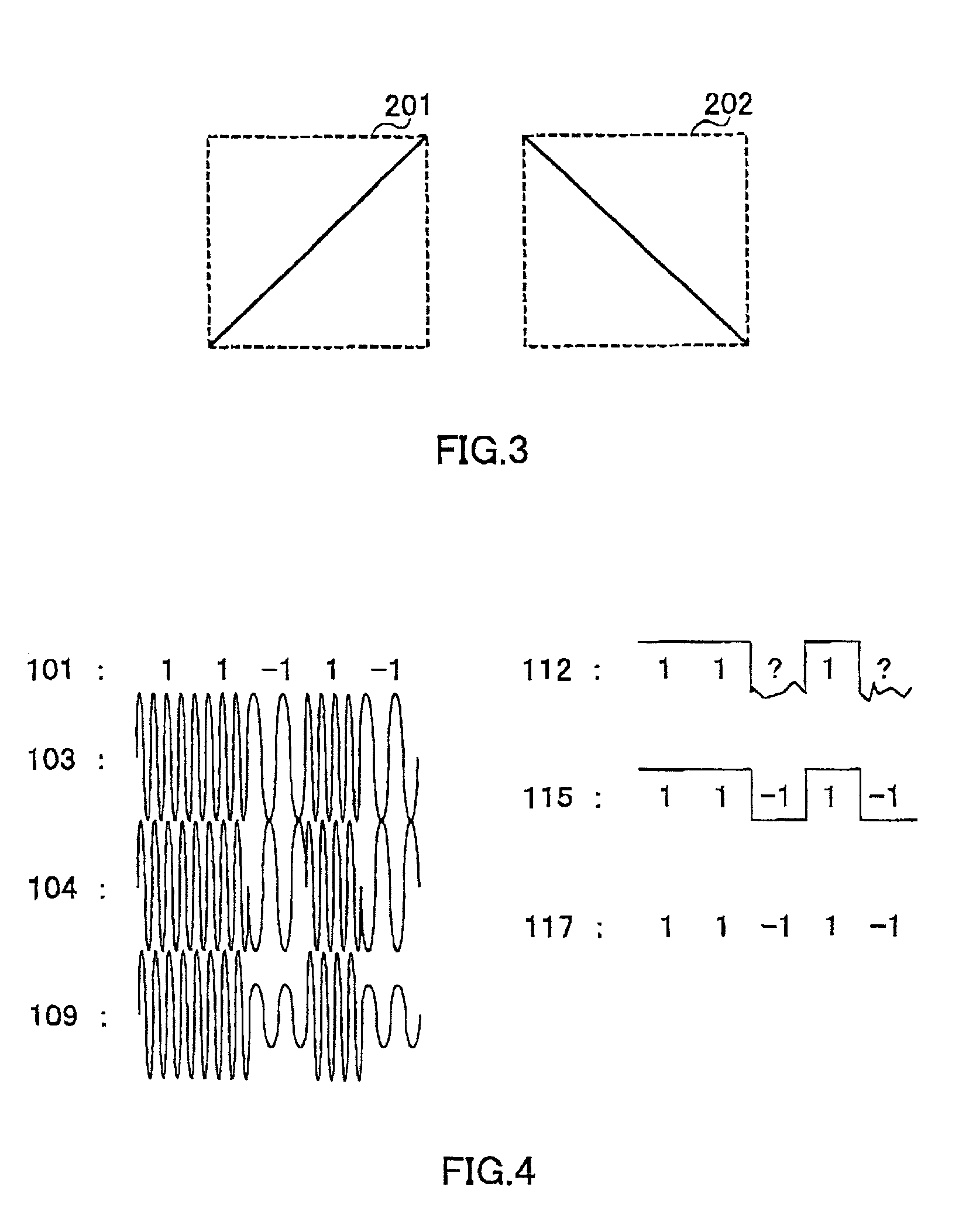
[0067]This embodiment explains a case of switching two antennas providing different planes of polarization perpendicular to each other as the method of transmitting signals with different planes of polarization in the radio transmission apparatus in the first embodiment. FIG. 9 is a block diagram illustrating a configuration of the radio transmission apparatus in the third embodiment of the present invention.

[0068]Switch 127 switches first antenna 128 and second antenna 129 providing different planes of polarization perpendicular to each other depending on transmission data 101. That is, switch 127 judges whether to transmit a signal from first antenna 128 or second antenna 129 corresponding to transmission data 101 to switch as appropriate. In addition, it is predetermined that which antenna is used to transmit a signal corresponding to what value of transmission data.

[0069]Thus according to this embodiment, signals are transmitted with different planes of polarization correspondin...


PUM


Abstract

Corresponding to transmission data 101, phase controller 105 is controlled to shift a phase of modulated signal 103 by 0° or 180°. Planes of polarization of modulated signals to be transmitted from antennas 106 and 107 are made different from each other corresponding to transmission data 101. The electric field strength of a signal received at antenna 108 changes corresponding to the plane of polarization, thereby voltage value 113 output from electric field strength detector 111 varies corresponding to transmission data 101, and using this variation, judged result 115 is obtained. Two results, namely, demodulated data 112 and judged result 115 are input to comparing circuit 116, whereby the reception apparatus is capable of obtaining received data 117 with high quality.

Description

BACKGROUND OF THE INVENTION[0001]1. Field of the Invention[0002]The present invention relates to a radio transmission apparatus and radio reception apparatus in a digital radio communication.[0003]2. Description of the Related Art[0004]Digital radio communications always have a possibility that a received electric field strength of a signal becomes weak due to geographical conditions because a space is used as a transmission medium. Therefore, when the received electric field strength of the signal is weak, an error rate of data is increased and the data quality deteriorates. An example of measures to cope with the above situation is a technique using a polarization modulation as described in Japanese Laid Open Patent Publication HEI4-276926.[0005]This technique uses a modulation system that represents “1” and “0” of data with polarizations. Specifically in the technique, a transmission apparatus and reception apparatus each is provided with two antennas with different directivities...

Claims


Application Information

Patent Timeline
IPC IPC(8): H04B1/06H04B7/00H04B7/10
CPCH04B7/10
Inventor MIYANO, KENTARONAKAGAWA, YOUICHIMIMURA, MASAHIROHASEGAWA, MAKOTOKOYANAGI, YOSHIO
Owner PANASONIC CORP
Why Eureka
Try Eureka