Root complex connection system

a complex connection and root technology, applied in the field of root complex connection system, can solve the problems of increasing system latency, increasing cost, size and complexity of switch, and increasing system latency, so as to reduce the cost and complexity of data processing devices, and reduce the latency of the system

Active Publication Date: 2006-06-13
EMC IP HLDG CO LLC
View PDF7 Cites 57 Cited by
  • Summary
  • Abstract
  • Description
  • Claims
  • Application Information

AI Technical Summary

Benefits of technology

[0010]The present invention is directed to a data processing system that utilizes two identical data processing devices. The storage processors of each data processing device communicate with each other across the midplane utilizing a non-transparent bridge device in each data processing device that is responsible for handling less than all of the data lanes that connect the first and second data processing devices. The non-transparent bridges are smaller in size than the prior art non-transparent bridges, and thus reduce the cost and complexity of the data processing devices. Furthermore, because the data on any particular lane only passes through one non-transparent bridge, the latency of the system is reduced by as much as half when compared to the prior art system.

Problems solved by technology

However, because the process of writing data to a disk drive takes much longer than the amount of time required by the storage processor to process incoming data, the data is stored in cache memory before it is finally written to the disk drive.
Therefore, any data transmitted from one storage processor to the other must pass through two non-transparent bridges, which increases the latency of the system.
Furthermore, the cost, size and complexity of the switch is increased because of the additional hardware required for two full eight lane non-transparent bridges.

Method used


Image

  • Root complex connection system
  • Root complex connection system
  • Root complex connection system

Examples


Embodiment Construction

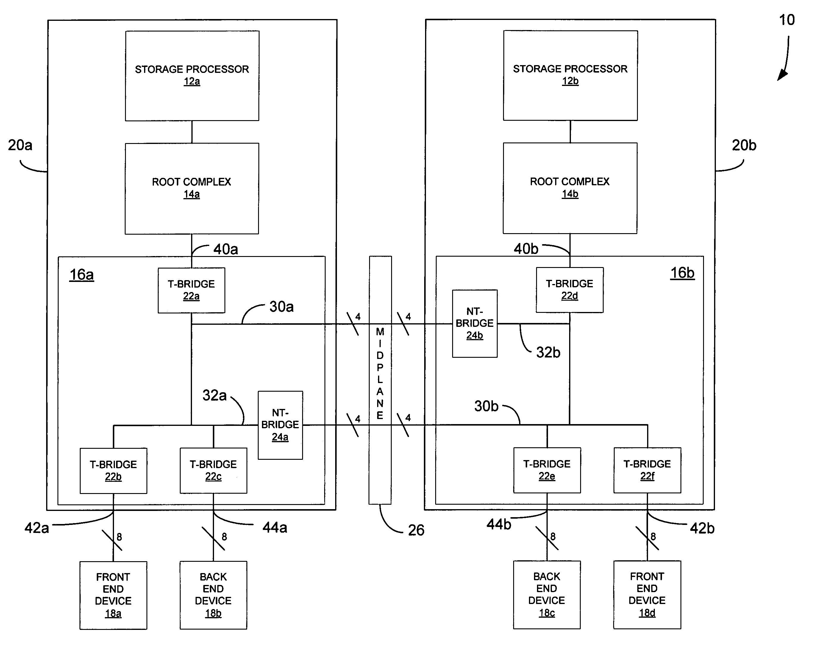
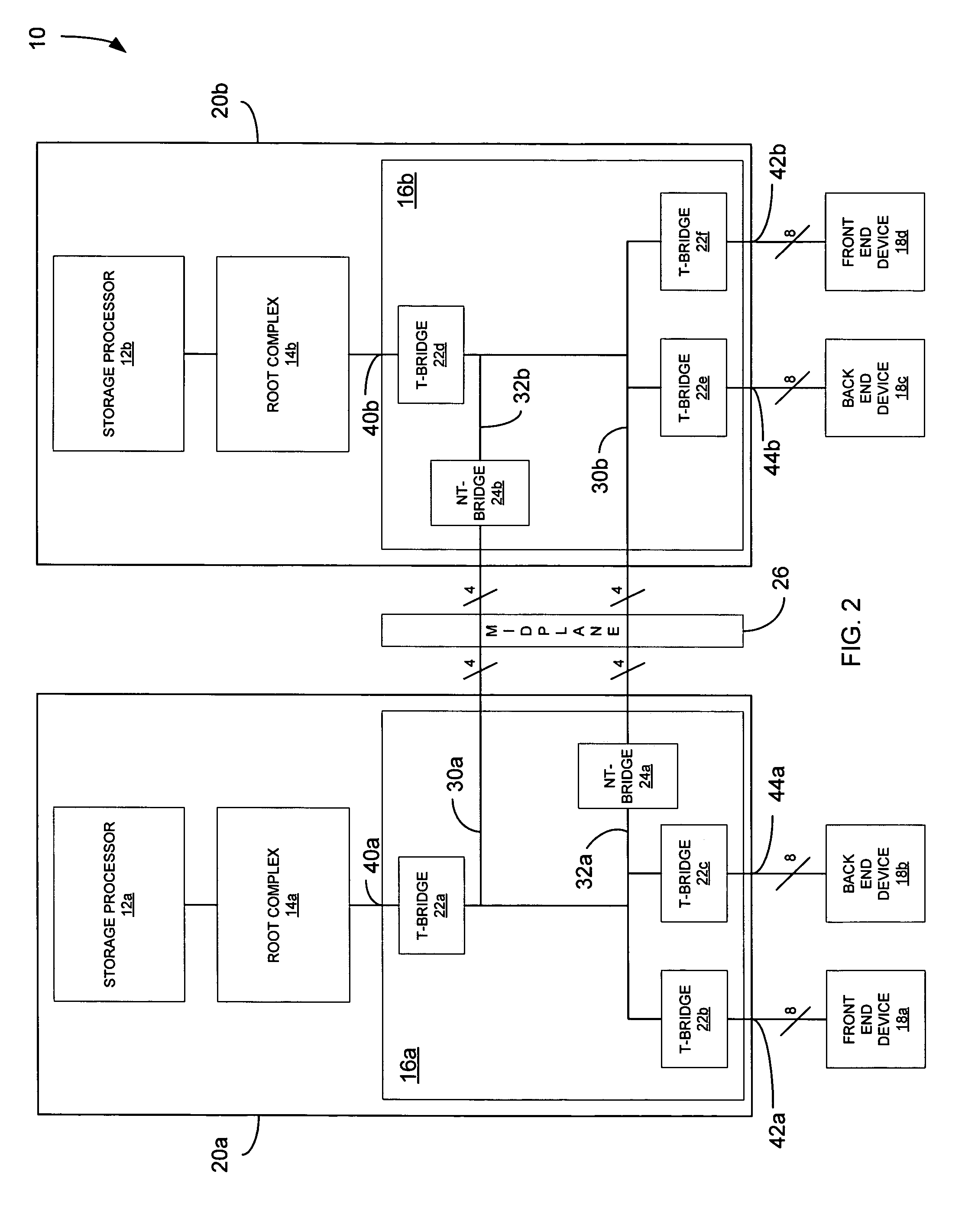
[0017]FIG. 2 is a schematic diagram of a data storage system 10 according to the present invention that utilizes transparent and non-transparent bridges. The system 10 includes a first data processing device 20a and a second data processing device 20b. Data processing devices 20a and 20b are identically configured, thus enabling the design and manufacture of a single part, to reduce development and manufacturing costs. Each data processing device 20a, 20b includes a storage processor 12a, 12b, which controls the operation of the data processing device. A root complex 14a, 14b is connected between the storage processor 12a, 12b and a switch device 16a, 16b. The root complex 14a, 104b is the PCI-Express version of a Northbridge, and transmits data between the storage processor 12a, 12b and the switch 16a, 16b. While this embodiment of the invention is described as implementing the PCI-Express protocol, it will be understood that any serialized bus LVDS protocol may be utilized in the ...


PUM


Abstract

A data processing system includes first and second data processing devices coupled to each other through a midplane. Each data processing device includes a data storage processor; a root complex coupled to the data storage processor; and a switch device coupled between the root complex and at least one end point device. The switch device includes a first transparent bridge coupled to the root complex and a second transparent bridge coupled between the first transparent bridge and the at least one end point device, a first data path connected between the first transparent bridge and the midplane and a second data path connected between the first transparent bridge and the midplane through a non-transparent bridge. The first data path of the first data processing device is connected to the second data path of the second data processing device through the midplane and the second data path of the first data processing device is connected to the first data path of the second data processing device through the midplane, such that data transmitted between the root complexes of each of the first and second data processing devices is transmitted through only one non-transparent bridge.

Description

FIELD OF THE INVENTION[0001]The present invention is directed generally to a root complex connection system and, more particularly, to a system for connecting two root complexes through redundant low-voltage differential signaling (LVDS) protocol paths using minimal non-transparent connections.BACKGROUND OF THE INVENTION[0002]Data storage systems can include two storage processors for handling the data processing and caching operations of the storage system. The two storage processors enable the system to perform up to twice as much work in parallel than a single processor and enable the system to be cache-enabled. Write data that is processed by the storage processors is eventually written to disk drives in the disk drive array. However, because the process of writing data to a disk drive takes much longer than the amount of time required by the storage processor to process incoming data, the data is stored in cache memory before it is finally written to the disk drive. This type o...

Claims


Application Information

Patent Timeline
Patent Type & Authority Patents(United States)
IPC IPC(8): G06F13/36G06F13/00
CPCG06F13/4027
Inventor SARDELLA, STEVEN D.SULLIVAN, DOUGLAS
Owner EMC IP HLDG CO LLC
Why Eureka
Try Eureka